
Subsea umbilical

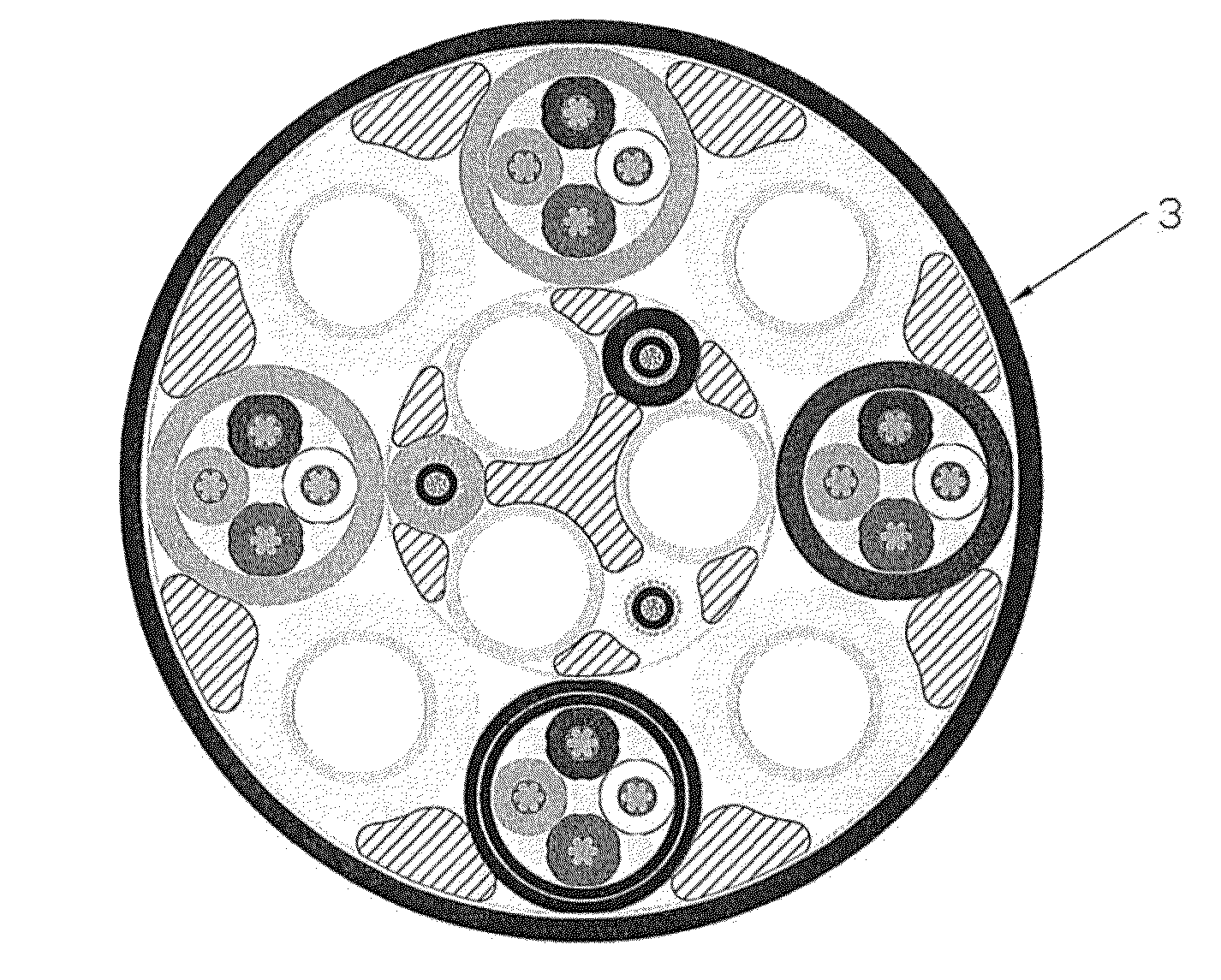
a technology of umbilicals and subsea, applied in the field of subsea umbilicals, can solve the problems of not meeting the required w/d ratio, unable to solve, and the outer diameter of the umbilical is larger than the outer diameter, and achieves the effect of more seabed stability

Active Publication Date: 2016-05-12
NEXANS
View PDF6 Cites 0 Cited by
  • Summary
  • Abstract
  • Description
  • Claims
  • Application Information

AI Technical Summary

Benefits of technology

The present invention provides an improved design for an umbilical that can be used in subsea applications. The design includes a sheath made of a polymer composite that has a specific weight to diameter ratio and minimum submerged weight per length. The polymer composite has a high density filler, such as metal or chromium, which helps to reduce the weight of the sheath. The use of a polymer composite with a high density filler in the sheath helps to achieve a minimum submerged weight to length, which is important for the performance of the umbilical. The polymer composite can be made of HDPE, PE, PP, PU, PA, or PBT. The invention also provides a method for manufacturing the improved design of the umbilical. Overall, the invention provides a more efficient and lightweight design for subsea applications.

Problems solved by technology

Moreover, the alternative method using traditional outer armouring causes the umbilical to have a larger outer diameter.
Thus, in many instances there is presently no solution for obtaining a subsea umbilical having a compact cross section, and which fulfils a required w / d ratio.
In addition to an increased cross section, the use of excess steel armouring increases the cost of the umbilical.
Said increase is both due to increased material costs and a more complicated manufacturing process.

Method used


Image

  • Subsea umbilical
  • Subsea umbilical

Examples


Embodiment Construction

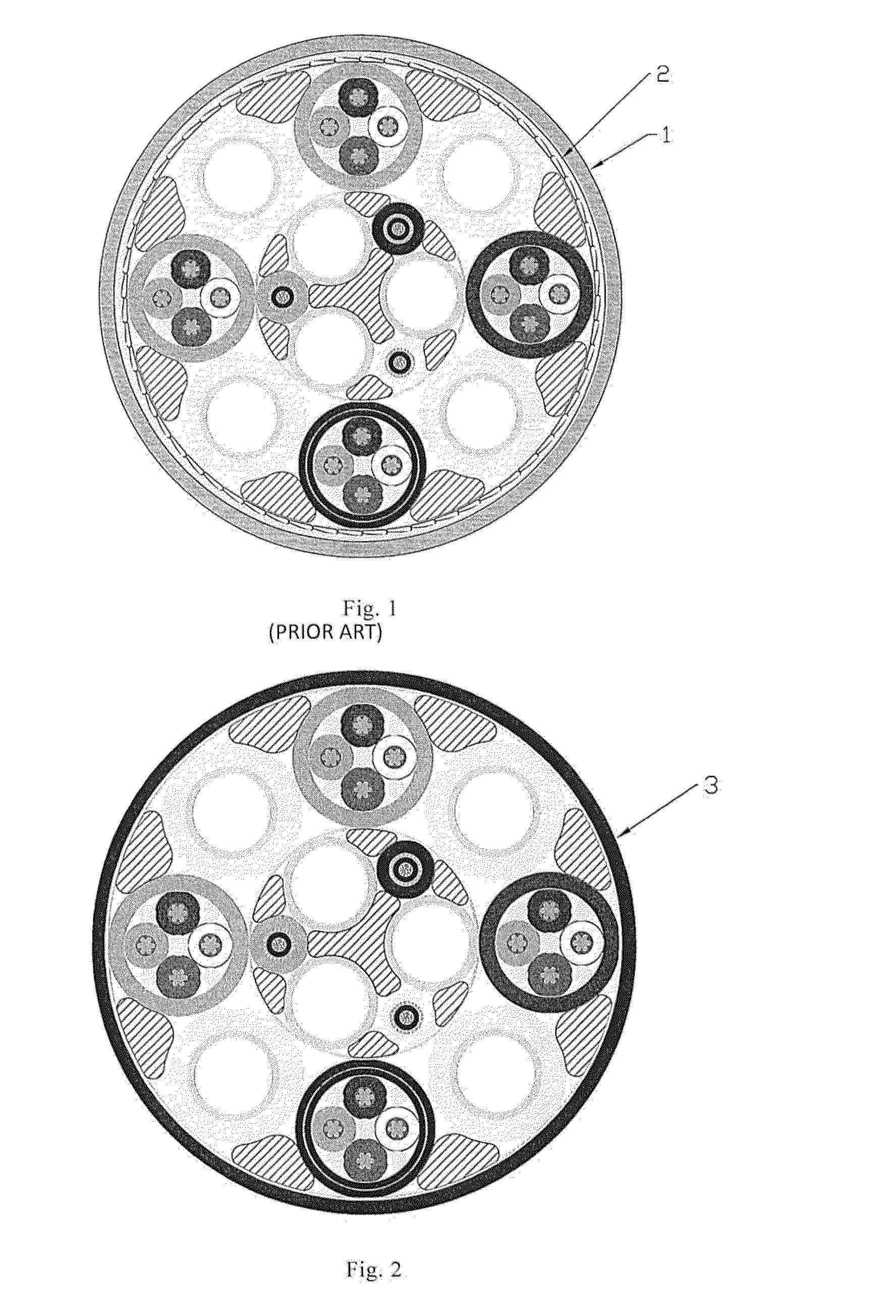
[0035]A subsea umbilical comprising a prior art solution for obtaining a specific w / d ratio, minimum submerged weight per length (kg / m), or specific gravity, is shown in FIG. 1. The cross sectional view is of a 127 km long umbilical which the applicant delivered to Total for the Laggan Tormore field. This specific umbilical comprises multiple hydraulic lines comprising a steel tube and a surrounding high density polyethylene (HDPE) sheath, multiple electrical quads, fibre optic elements, PP filler, profiled PE filler, PP yarn and an outer HDPE sheath 1. To achieve a required specific gravity of 1.82 in seawater (corresponding to a submerged weight to diameter ratio of 81.8 kg / m), 4 layers of steel tape 2 were added to the umbilical. Both the specific gravity and the weight to diameter ratio are calculated based on the tubes and interstices of the umbilical being flooded with seawater. The minimum submerged weight per length (kg / m) is similarly calculated based on the tubes and inter...


PUM

PropertyMeasurementUnit
densityaaaaaaaaaa
densityaaaaaaaaaa
densityaaaaaaaaaa

Abstract

An umbilical for subsea applications has at least one longitudinal internal element and a sheath, the sheath is formed by extrusion. The internal element is suitable for communicating fluids, electrical power or signals, or for carrying loads. The sheath is made of a polymer composite having a high density filler, the polymer composite having a density in the range 3 to 11 g / cm3.

Description

FIELD OF INVENTION[0001]The present invention concerns subsea umbilicals having a required weight to diameter ratio.BACKGROUND[0002]Subsea umbilicals often require a specific weight to diameter ratio and / or a minimum submerged weight to achieve on-bottom stability. The specific weight to diameter ratio is often a customer requirement and depends on the intended application.[0003]Presently, to fulfil higher weight to diameter (w / d) ratio requirements, excess steel armour is commonly applied to the umbilical. The amount of steel armour required to obtain the w / d ratio thus exceeds the amount required for sufficient mechanical strength.[0004]The excess steel armour comprises either polyethylene (PE)-sheathed steel wires incorporated in the umbilical during the lay-up process, or steel armouring wound around the element bundle of the umbilical after lay-up (traditional armouring process).[0005]The present methods for achieving a specific w / d ratio present a number of disadvantages. To a...

Claims


Application Information

Patent Timeline
Patent Type & Authority Applications(United States)
IPC IPC(8): B05D7/20E21B17/00E21B17/01
CPCB05D7/20E21B17/003E21B17/01H01B7/045H01B7/14H01B7/17H01B7/18F16L11/127H01B7/0072H01B7/187
Inventor EGGERTSEN, CARL FREDRIK
Owner NEXANS
Learn More