
Measurement Control System for Multi-Shaft Supported Air Floatation Platform

a technology of floatation platform and control system, which is applied in the direction of electric programme control, program control, instruments, etc., can solve the problems of unstable leveling, low comfort level of operators, and low safety coefficient, and achieve high leveling precision, short adjustment time, and great load-bearing capacity

Active Publication Date: 2016-05-05
HARBIN INST OF TECH
View PDF4 Cites 29 Cited by
  • Summary
  • Abstract
  • Description
  • Claims
  • Application Information

AI Technical Summary

Benefits of technology

The present invention is a versatile simulator for space rendezvous and docking. It features a strong and accurate leveling system. The platform can quickly and accurately adjust to the needs of the user, ensuring high precision, stability, and reliability. This results in a highly leveled workspace, ideal for practical engineering applications. The platform can easily load and adjust to changes in demand, ensuring high precision in leveling, both in dynamic and static states.

Problems solved by technology

Since the platform at both dynamic or static states may be in an inclined state due to the unevenness of the large surface level base platform, which is unfavorable for providing a level working platform for the loading to ensure accurate docking, it is required to level the platform speedily and accurately at both dynamic or static states so as to ensure that sufficient degree of levelness is maintained.
(1) The gravity (weight) leveling mechanism processes leveling of the work platform based on weight and is composed of the work platform and the frame. This type of leveling is unstable, its safety coefficient is low and the comfort level for the operators is low.
(2) The four-rod leveling mechanism utilizes the physical properties of the four rods for leveling the work platform and the disadvantages are inapplicable to telescopic arms and narrow application range.
(3) The isovolumetric hydraulic leveling mechanism utilizes passive cylinder installed on the luffing arm and isovolumetric leveling hydraulic cylinder installed on the work platform for leveling the work platform, which includes work platform, passive cylinder and isovolumetric leveling hydraulic cylinder. The disadvantages are inapplicable to multi-staged telescopic arms and narrow application range.

Method used


Image

  • Measurement Control System for Multi-Shaft Supported Air Floatation Platform
  • Measurement Control System for Multi-Shaft Supported Air Floatation Platform
  • Measurement Control System for Multi-Shaft Supported Air Floatation Platform

Examples


embodiment 1

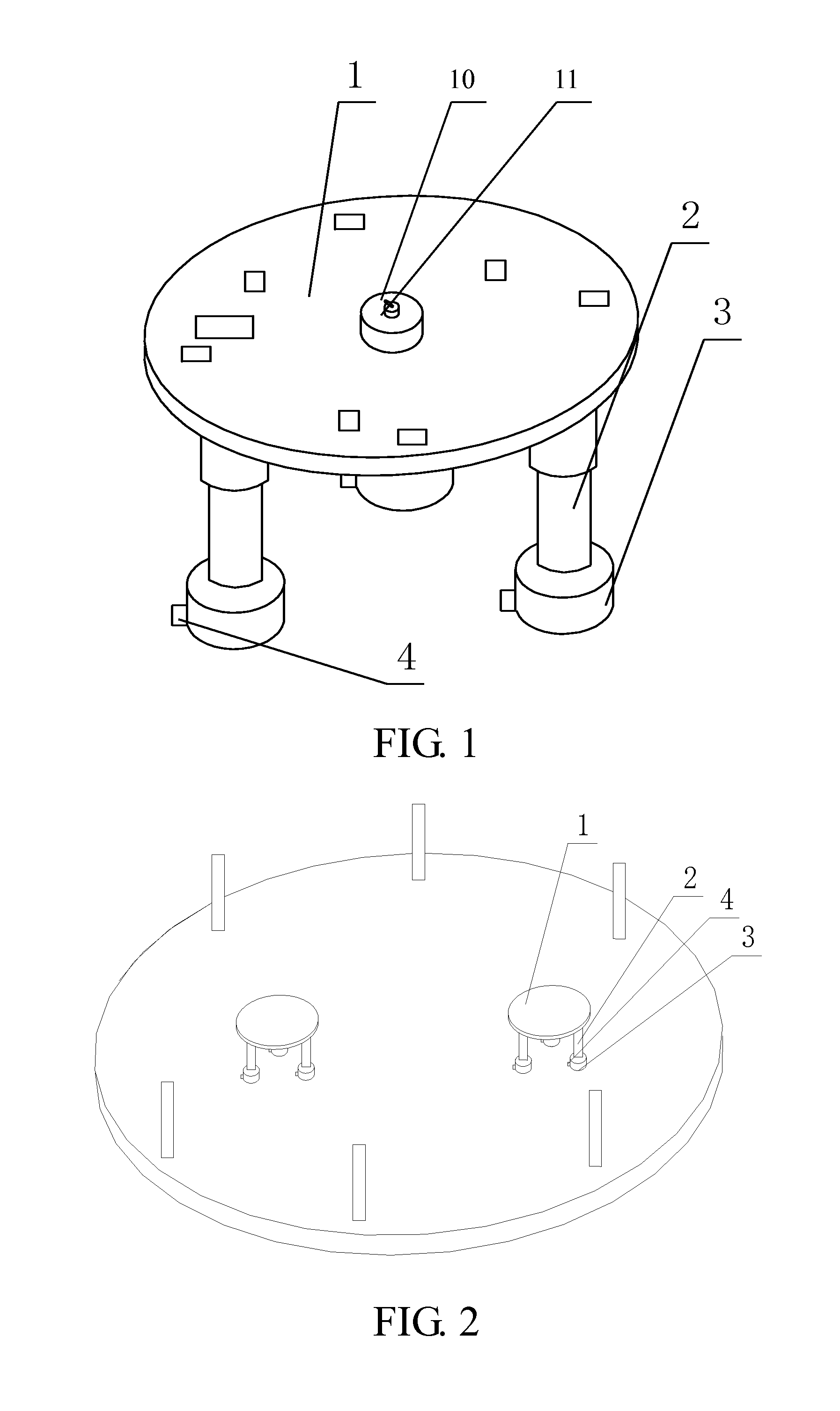
[0042]This embodiment is further described in connection with FIG. 1 to FIG. 9 as follows. The measurement and control system for multi-axis supported floatation platform of this embodiment carries out the measurement and control process for the multi-axis supported floatation platform. The multi-axis floatation platform includes a load platform 1, M number of support legs 2, M number of floatation cylinders 3 and M number of gas bearings 4, where M is 3, 4, 5, 6, 7 or 8.

[0043]The load platform 1 is a round platform. The load platform 1 is supported by M number of support legs 2. The M number of support legs 2 are connected to M number of connecting points at the bottom surface of the load platform 1 such that a regular M-polygon is constructed.

[0044]Each support leg 2 has one end connected to a floatation cylinder 3. Each floatation cylinder 3 has a bottom end connected to one gas bearing 4 through floatation ball bearing.

[0045]The measurement and control system includes a load fee...

embodiment 2

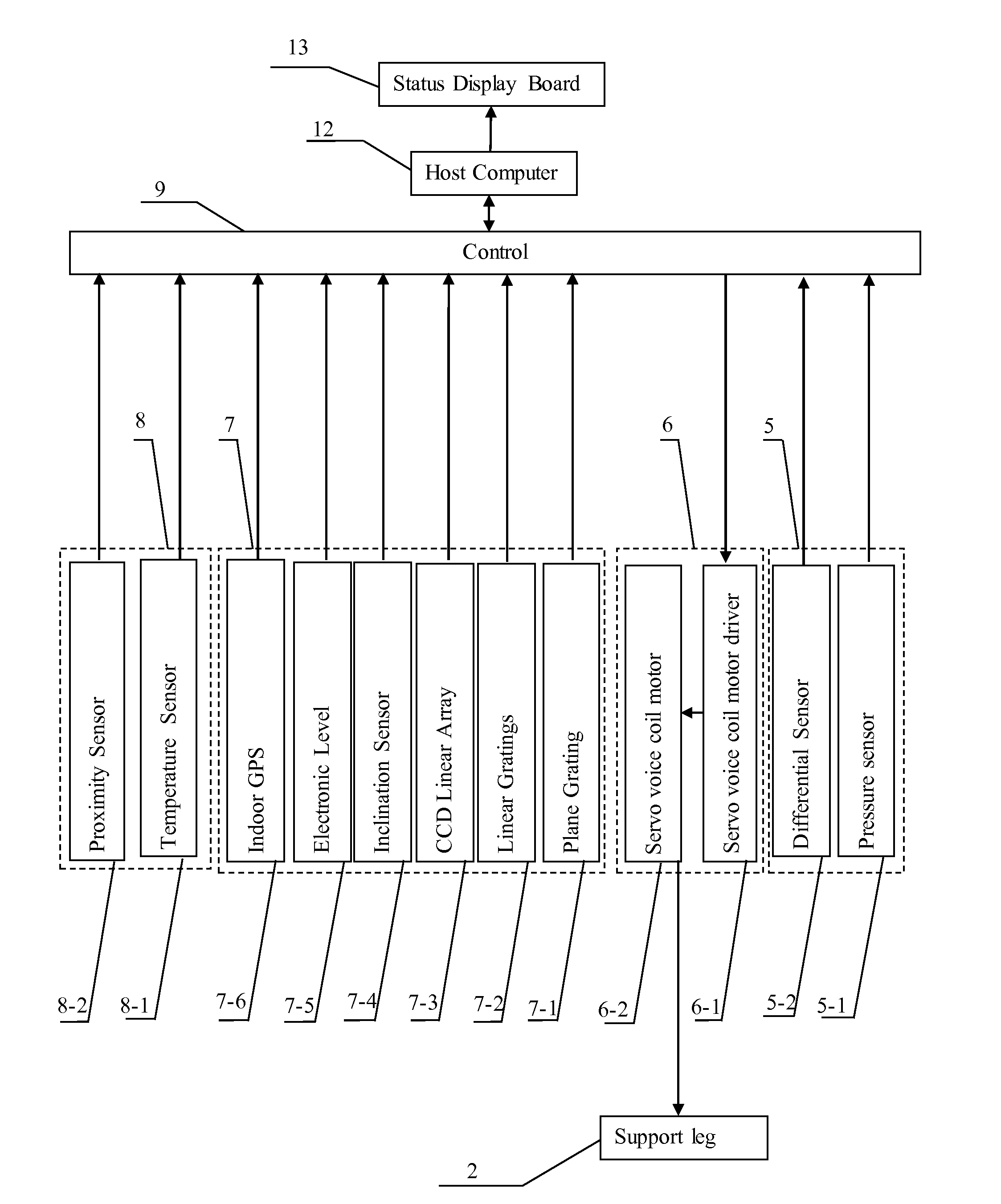
[0059]This embodiment is further described in connection with FIG. 9 as follows. This embodiment provides further description for embodiment 1. According to this embodiment, the measurement and control system further comprises a host computer 12 and a status display board 13.

[0060]The host computer 12 has a signal transmission terminal connected to the signal transmission terminal of the control 9. The host computer 12 has a display signal output terminal connected to the display signal input terminal of the status display board 13.

embodiment 3

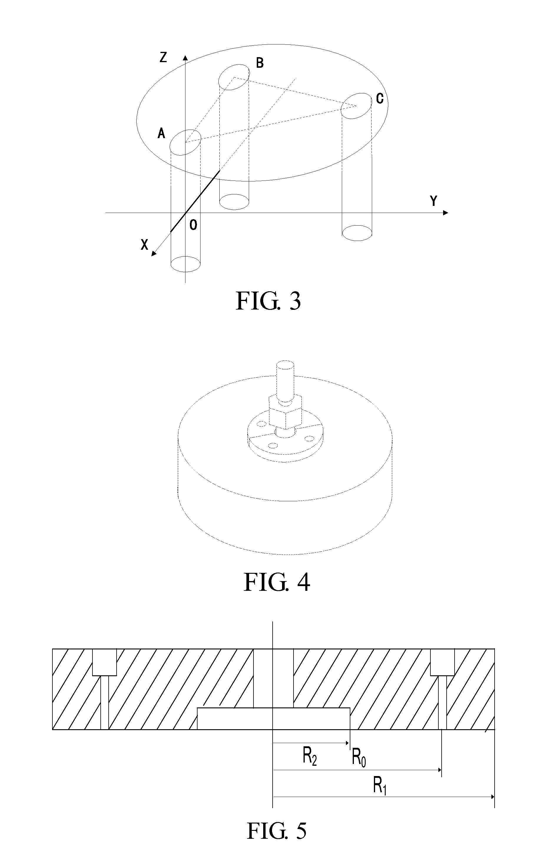
[0061]This embodiment is further described in connection with FIG. 1 to FIG. 10 as follows. This embodiment provides further description for embodiment 1 or 2. According to this embodiment, the M number of support legs 2 are three support legs, the radius of the load platform 1 is 2 m, the three support legs 2 connected to the bottom surface of the load platform 1 through three connecting points to form an equilateral triangle, the distance between the vertex of the equilateral triangle and the center of the load platform 1 is 1.4 m.

[0062]As shown in FIG. 3 of the drawings, the support legs 2 of the multi-axis supported floatation platform and the three connecting points A, B and C of the bottom surface of the load platform 1 forms an equilateral triangle and the length of each side is L=2424 mm. The gas bearings 4 utilizes compressed air to form a film between the floatation ball bearings and ball sleeves to realize the approximate frictionless motion, so as to simulate the dynamic...


PUM


Abstract

A measurement control system for a multi-shaft supported air floatation platform, the system comprising a load feedback unit (5), an execution unit (6), a position measurement unit (7), a safety protection unit (8), a controller (9), a rotating motor (10), and a linear light source 11; the load feedback unit comprises M pressure sensors (5-1) and four differential sensors (5-2); the execution unit comprises M servo voice coil motors (6-1) and M servo voice coil motor drivers (6-2); the position measurement unit comprises a plane grating (7-1), M linear gratings (7-2) a linear array CCD (7-3), a tilt sensor (7-4), M electronic levels (7-5), and an indoor GPS (7-6); the safety protection unit comprises 2M proximity sensors (8-1) and M temperature sensors (8-2); and the linear array CCD consists of no few then six CCDs. The system solves the problems of leveling limitations and narrow application range of existing supporting platforms.

Description

CROSS REFERENCE OF RELATED APPLICATION[0001]This is a national phase national application of an international patent application number PCT / CN2014 / 076911 with a filing date of May 6, 2014, which claimed priority of one foreign application which is filed in China: application number 201310187886.0 and filing date May 20, 2013. The contents of these specifications, including any intervening amendments thereto, are incorporated herein by reference.BACKGROUND OF THE PRESENT INVENTION[0002]1. Field of Invention[0003]The present invention relates to a measurement and control system for Multi-axis supported floatation platform, which belongs to the technical field of ultra-precision instrument and equipment platform.[0004]2. Description of Related Arts[0005]Nowadays, platforms at high level are needed frequently. For examples, in physical simulation experiments for space rendezvous and docking, ground measurement, navigation, network communication, formation control and etc., support is re...

Claims


Application Information

Patent Timeline
Patent Type & Authority Applications(United States)
IPC IPC(8): G05D3/12F16M11/26G05B19/27
CPCG05D3/12G05B2219/49276F16M11/26G05B19/27F16M11/121F16M11/18F16M11/32G05B15/02F16F15/00
Inventor CHEN, XINGLINLIU, YANGLI, CONGWANG, WEIFENGLIU, CHUAN
Owner HARBIN INST OF TECH
Learn More