
Assessment and calibration of a high energy beam

a beam and high energy technology, applied in the field of high energy beams, can solve the problems of only being able to analyze, generating and controlling high energy beams, and complex geometries,

Active Publication Date: 2016-05-05
HOWMEDICA OSTEONICS CORP
View PDF2 Cites 7 Cited by
  • Summary
  • Abstract
  • Description
  • Claims
  • Application Information

AI Technical Summary

Benefits of technology

The invention is a system that can accurately measure the characteristics of high energy beams across an entire processing area. This includes the parameters of current, shape, size, peak power distribution, and position of the beam. The system can measure these parameters quickly and accurately, even at high beam powers. The system can measure the parameters across a processing area and at speeds corresponding to normal processing conditions. The system produces repeatable and reproducible results with respect to the beam focal plane. The invention also includes a calibration procedure that accurately positions the beam in relation to the calibration plate. This enables highly accurate positional calibration using small holes or conductors in known locations. Overall, the invention improves the accuracy and efficiency of e-beam analysis and verification techniques, ensuring the reliability and repeatability of components manufacturing using high energy beam systems.

Problems solved by technology

Focused high energy beams, including electron beams (also referred to as “e-beams”) and laser beams have been used to melt layers of metallic powder, resulting in the generation of complex geometries.
The generation and control of a high energy beam is a rather complex process.
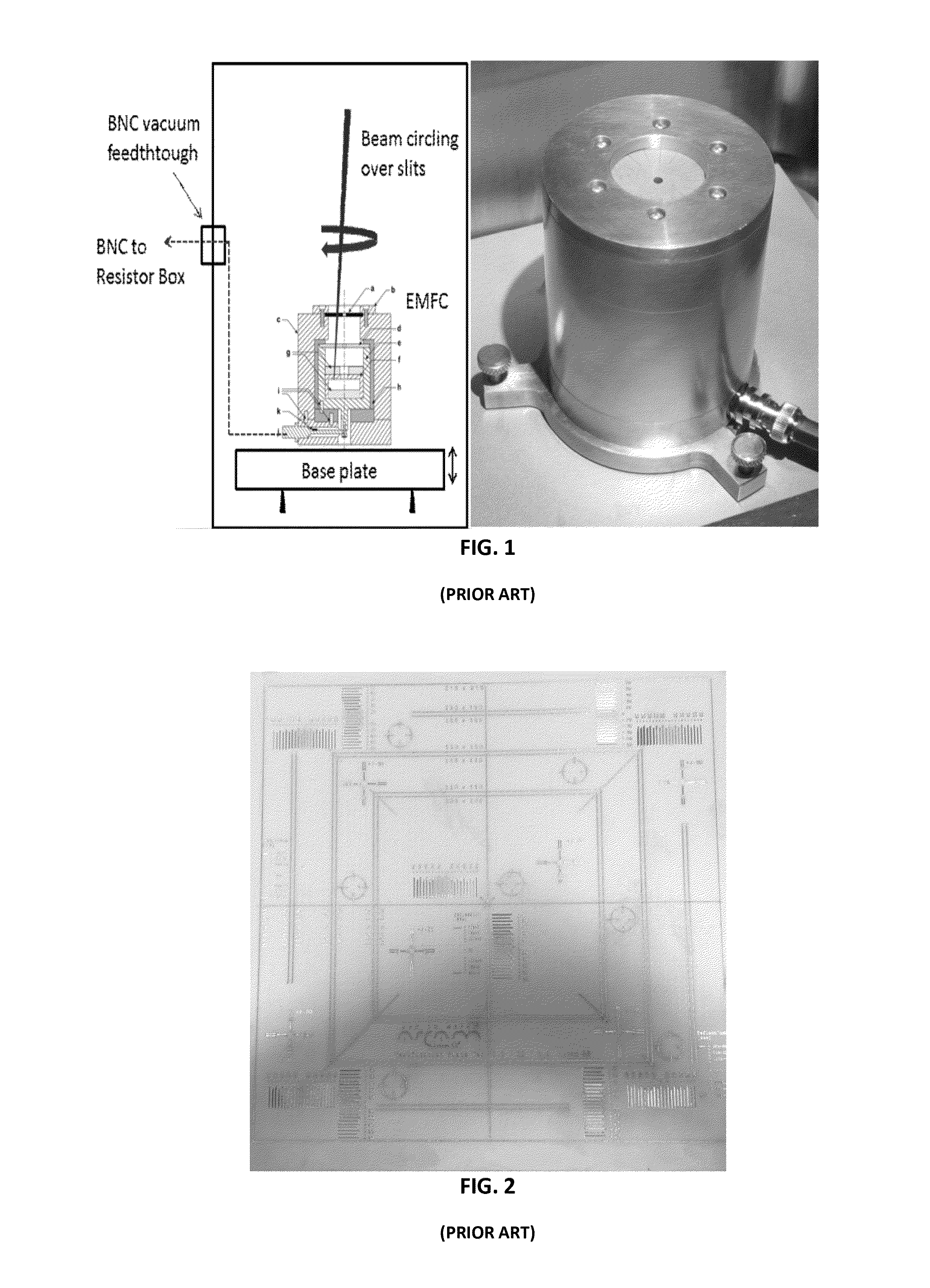
However, a major limitation with the EMFC system is that, due to the requirement for a beam undergoing testing to enter the tungsten disc at a specific angle, the EMFC is only able to analyze the beam in the center of a build area.
This limitation leads to an assumption that the measured beam characteristics are accurately replicated across an entire build area over which a beam will travel during manufacturing of a component.
However, the quantity of data generated by this process is insufficient to be used in the manufacture of reliably and reproducibly high quality components.
A further weakness of the beam calibration procedures is their dependence on operator skill leading to significant potential for error and lack of repeatability between successive beam calibrations.

Method used


Image

  • Assessment and calibration of a high energy beam
  • Assessment and calibration of a high energy beam
  • Assessment and calibration of a high energy beam

Examples


Embodiment Construction

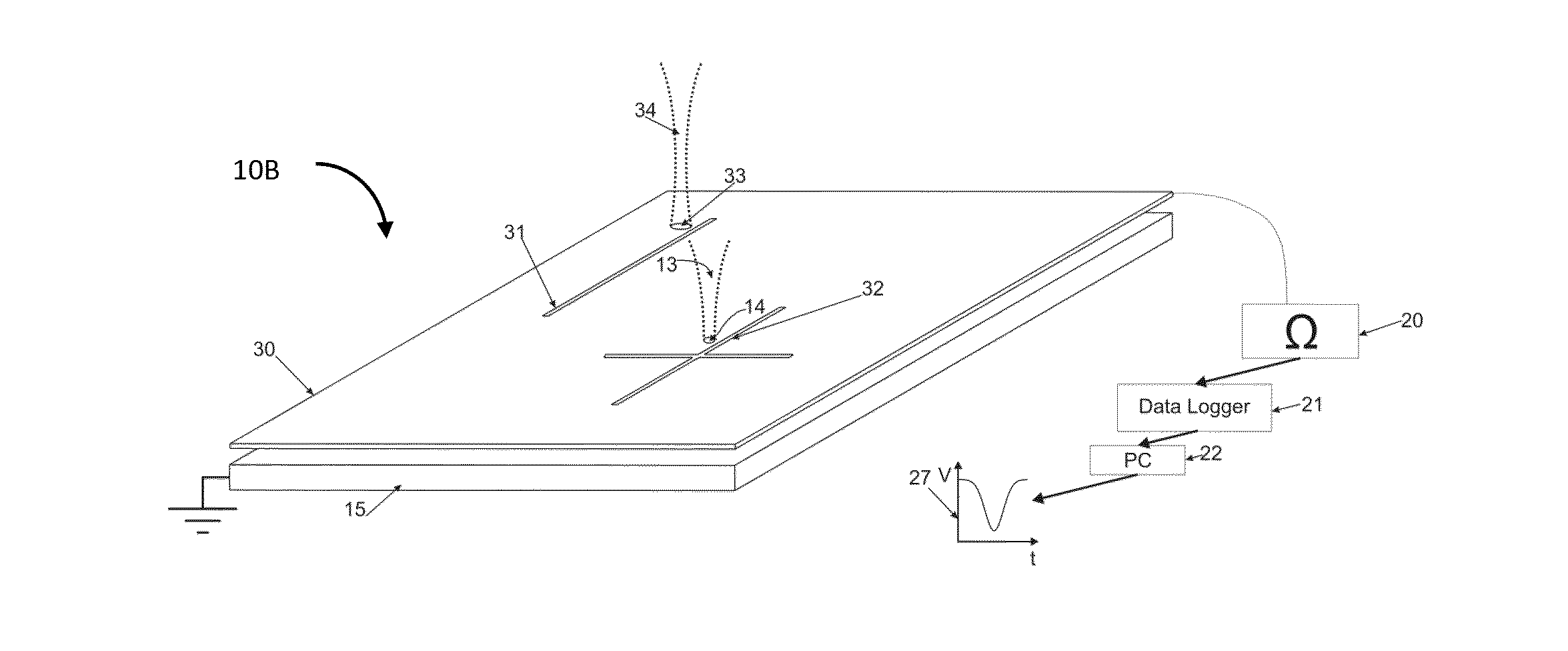
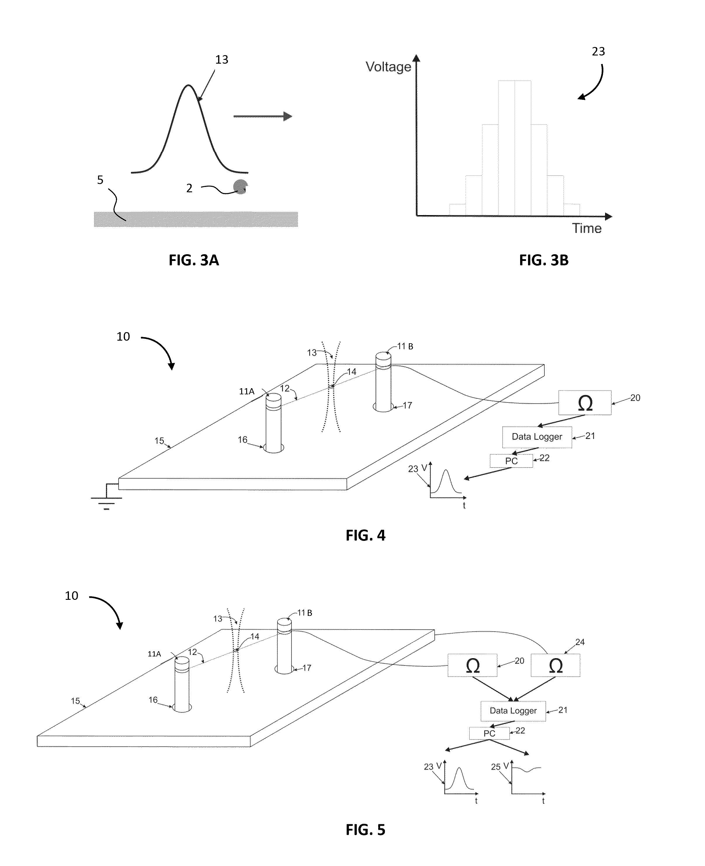
[0078]Referring to the drawings, as shown in FIGS. 3A and 3B, electron beam 13 may be translated over conductive plate 5, which may be but is not limited to steel, and may traverse thin cylindrical wire 2, which may be a tungsten wire, to produce a voltage drop. As shown in FIG. 3B, the voltage drop may increase as the high energy beam traverses thin wire 2 until the point of maximum energy crosses the thin wire 2, preferably as measured in a direction transverse to a longitudinal axis of thin wire 2.

[0079]As shown in FIG. 4, in a single wire high energy beam profiling apparatus 10 in accordance with an embodiment, thin wire 12 defining a profile thereof may be suspended between two pillars 11A, 11B and pass through conductive plate 15 which may be grounded. Thin wire 12 may be insulated from conductive plate 15 by either passing through holes 16, 17 in conductive plate 15 or passing through insulated pillars 11A, 11B. High energy beam 13 then may be scanned across thin wire 12 to c...


PUM


Abstract

A high energy beam verification, calibration, and profiling system includes a conductive base plate, supports extending from the base plate, a plurality of conductors, a data logger electrically connected to the conductors, and a computer electrically connected to the data logger. Each conductor is supported by some of the supports such that each conductor is insulated from the conductive base plate. Each conductor has a profile intersecting with profiles of at least some of the other conductors to define a multidirectional and two-dimensional array of conductors. The data logger receives and records data associated with electrical charges flowing through the conductors. The computer is adapted to receive, manipulate, and display the data recorded by the data logger for comparison of beam characteristics at different locations across a high energy beam build area.

Description

CROSS-REFERENCE TO RELATED APPLICATIONS[0001]The present application claims the benefit of the filing date of U.S. Provisional Patent Application No. 62 / 075,584 filed Nov. 5, 2014, the disclosure of which is hereby incorporated herein by reference.FIELD OF THE INVENTION[0002]The present invention relates generally to high energy beams used in additive manufacturing, and in particular relates to the analysis, calibration, and profiling of such beams.BACKGROUND OF THE INVENTION[0003]Focused high energy beams, including electron beams (also referred to as “e-beams”) and laser beams have been used to melt layers of metallic powder, resulting in the generation of complex geometries. The quality and consistency of a high energy beam is one of the most important factors in determining the final quality of components manufactured using high energy beam melting processes. The generation and control of a high energy beam is a rather complex process. Two current methods used for assessing the ...

Claims


Application Information

Patent Timeline
Patent Type & Authority Applications(United States)
IPC IPC(8): G01R19/00G01T1/29
CPCG01T1/29G01R19/0061H01J37/244H01J2237/24405H01J2237/30477H01J2237/3114H01J2237/3128H01J37/02
Inventor MULLEN, LEWISROBINSON, JOSEPH
Owner HOWMEDICA OSTEONICS CORP
Learn More