Combustion control apparatus for internal combustion engine

a combustion control and internal combustion engine technology, applied in the direction of electric control, ignition automatic control, machines/engines, etc., can solve the problems of generating a large amount of nox and the inability to remove the nox contained in the exhaust gases, so as to reduce the air-fuel ratio. , the effect of reducing the air-fuel ratio

Active Publication Date: 2016-04-28
HONDA MOTOR CO LTD
View PDF8 Cites 16 Cited by
  • Summary
  • Abstract
  • Description
  • Claims
  • Application Information

AI Technical Summary

Benefits of technology

[0022]With this configuration, the control switch timing is a timing at which the catalyst temperature parameter reaches the predetermined temperature. The second temperature rise acceleration control becomes effective after the timing at which the catalyst temperature reaches the predetermined temperature. Accordingly, remarkable temperature rise acceleration effect can be obtained by performing the second temperature rise acceleration control from the time the catalyst temperature parameter exceeds the predetermined temperature.
[0023]Preferably, the second temperature rise acceleration control means reduces the air-fuel ratio (AF), advances the spark discharge start timing (CAIG), and reduces the spark discharge continuation time period (TSPK), as the catalyst temperature parameter increases.
[0024]With this configuration, the control in which the air-fuel ratio is reduced, the spark discharge start timing is advanced, and the spark discharge continuation time period is reduced, as the catalyst temperature parameter increases, is performed. The three-way catalyst containing platinum has a characteristic that the purifying performance becomes higher as the air-fuel ratio approaches the stoichiometric air-fuel ratio when the catalyst temperature becomes high. Accordingly, by reducing the air-fuel ratio as the catalyst temperature parameter increases, it is possible to obtain high purifying performance. Further, stable combustion is obtained by reducing the air-fuel ratio when advancing the spark discharge start timing and reducing the spark discharge continuation time period. Consequently, by advancing the spark discharge start timing and reducing the spark discharge continuation time period as much as possible, the engine output can be increased and the energy efficiency can be raised.
[0025]Preferably, the second temperature rise acceleration control means controls strength of the flow of the air-fuel mixture to a comparatively high degree at the beginning of the second temperature rise acceleration control, and gradually reduces the strength of the flow from the time (t2) the air-fuel ratio is reduced to a value in the vicinity of the first lean air-fuel ratio (AFTRA1).
[0026]With this configuration, the strength of the flow is controlled to a comparatively high degree at the beginning of the second temperature rise acceleration control, and the strength is gradually reduced from the time the air-fuel ratio is reduced to a value in the vicinity of the first lean air-fuel ratio. Reduction in the air-fuel ratio prevents the combustion from becoming unstable when the strength of the flow is reduced. Accordingly, it is possible to reduce the strength of the flow, thereby reducing heat loss of the combustion and improving thermal efficiency.

Problems solved by technology

In this lean air-fuel mixture combustion technique, NOx contained in the exhaust gases cannot be removed by the three-way catalyst.
However, according to this technique, a comparatively large amount of NOx is generated by the combustion in the vicinity of the spark plug.

Method used


Image

  • Combustion control apparatus for internal combustion engine
  • Combustion control apparatus for internal combustion engine
  • Combustion control apparatus for internal combustion engine

Examples


Embodiment Construction

[0040]Preferred embodiments of the present invention will now be described with reference to the drawings.

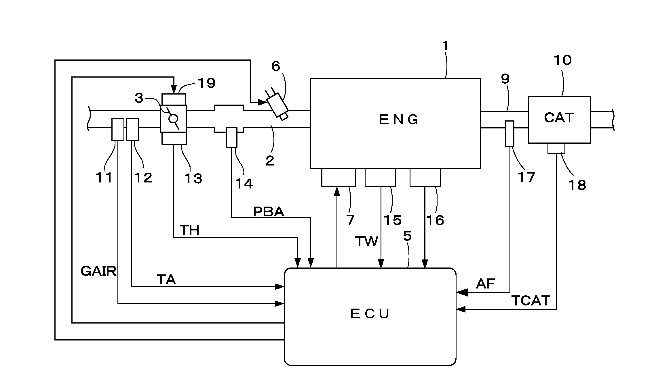
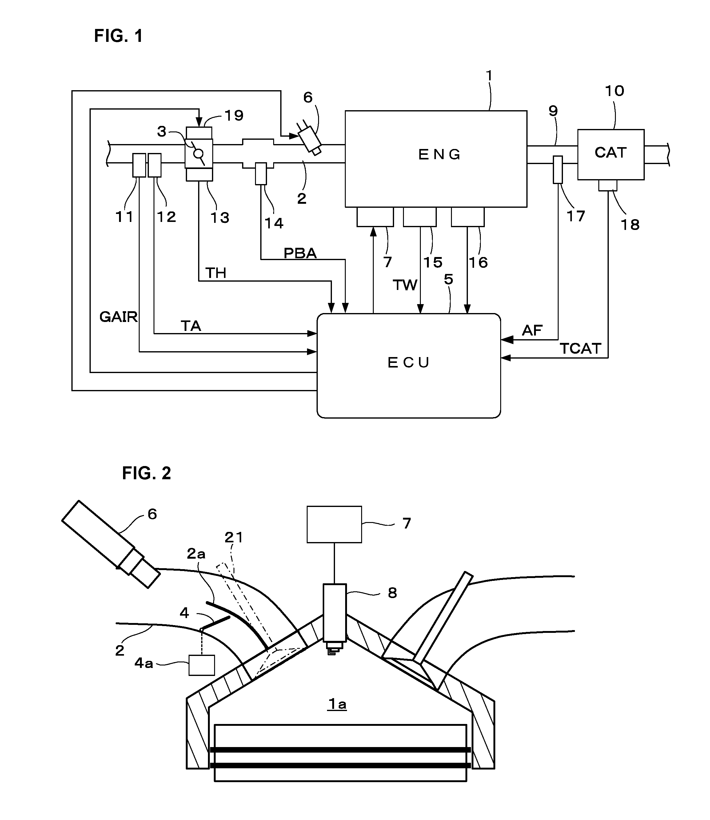
[0041]FIG. 1 shows a configuration of an internal combustion engine (hereinafter referred to as “engine”) and a control apparatus therefor according to one embodiment of the present invention. An intake passage 2 of the engine 1 having, for example, four cylinders is provided with a throttle valve 3. A fuel injection valve 6 is provided, corresponding to each cylinder, downstream of the throttle valve 3 in the intake passage 2. Operation of the fuel injection valve 6 is controlled by an electronic control unit (hereinafter referred to as “ECU”) 5.

[0042]As shown in FIG. 2, the intake passage 2 is provided with a partition wall 2a and a tumble flow control valve 4 which is disposed in one of the passages defined by the partition wall 2a. The tumble flow control valve 4 is configured so as to be opened and closed by an actuator 4a. The actuator 4a is connected to the ECU 5, and its...


PUM


Abstract

A combustion control apparatus for an internal combustion engine includes a spark plug for performing spark ignition of an air-fuel mixture in the combustion chamber, a plurality of coil pairs for generating spark discharge in the spark plug, and a fuel injection valve capable of injecting atomized fuel. Atomized fuel is injected into the intake passage, and a homogeneous lean air-fuel mixture is formed in the combustion chamber. The air-fuel ratio of the air-fuel mixture in the combustion chamber is controlled to be leaner than a predetermined lean air-fuel ratio. A spark discharge start timing and a spark discharge continuation time period are controlled using the plurality of coil pairs. The spark discharge start timing is set to a timing advanced from the spark discharge start timing for igniting a stratified lean mixture, such that the air-fuel ratio in the vicinity of the spark plug is relatively small.

Description

TECHNICAL FIELD[0001]The present invention relates to a combustion control apparatus for an internal combustion engine, and particularly to a combustion control apparatus in which a homogeneous lean air-fuel mixture is burned by spark ignition.BACKGROUND ART[0002]Lean air-fuel mixture combustion technique for performing the spark ignition of the lean air-fuel mixture (of which the air-fuel ratio is large) is well known, for example, as shown in Patent document 1 (shown below). In this lean air-fuel mixture combustion technique, NOx contained in the exhaust gases cannot be removed by the three-way catalyst. Accordingly, it is important to make the combustion limit air-fuel ratio become higher. Patent document 1 discloses a technique for stably burning the mixture of which the average air-fuel ratio in the combustion chamber is high, by stratifying the mixture so that a portion of the mixture having a relatively rich air-fuel ratio (small air-fuel ratio) exists in the vicinity of the ...

Claims


Application Information

Patent Timeline
Patent Type & Authority Applications(United States)
IPC IPC(8): F02D37/02F02P5/04F02D41/40F02P5/15F01N3/10F02D41/14
CPCF02D37/02F01N3/101F02P5/045F02D41/402F02P5/15F02D41/1461F01N13/008F01N2560/025F02D41/0002F02D41/0255F02D41/1456F02D41/3041F02D2200/0802F02P3/0453F02P5/1506F02P15/10Y02T10/12Y02T10/40
Inventor KONDO, TAKASHIHANABUSA, HIROSHIHASHIMOTO, KOHTARO
Owner HONDA MOTOR CO LTD
Why Eureka
Try Eureka