Pallet with impact guards

Inactive Publication Date: 2016-04-28
NEXTREME
View PDF0 Cites 12 Cited by
  • Summary
  • Abstract
  • Description
  • Claims
  • Application Information

AI Technical Summary

Benefits of technology

This patent describes a new deck and base pallet assembly that uses a snap together design to eliminate the problem of fusing two dissimilar materials. The assembly requires a high separation force to separate the deck and base, ensuring a robust assembly. The use of fire retardant materials and co-ex structures provides non-hazardous solutions, with a thicker underlying layer of composite HDPE or alternative resins. The pallet also eliminates vent holes and has a flat surface area, reducing the material exposed to fire. Additionally, the pallet can be used to change the regulations for idle pallet storage, improving safety and reducing the risk of theft and wear and tear.

Problems solved by technology

Wooden pallets however fall apart due to wear and tear in use so that wood pallet pooling companies have to charge their customers a significant pallet rental fee that includes the cost of required repeated repair of the wood pallet for continued re-use.
The long term operating costs of a wood pallet are therefore higher due to ongoing maintenance costs than the original cost of the long lasting plastic pallet, so that the original lower price advantage of wood is lost to plastic.
However, with the passage of time, it has been discovered that plastic pallets are also prone to wear and tear, presented by the effects of delamination, punctures, cracks and the like.
These problems are not presented in wood, so plastic pallets have unique problems only recently realized.
The prior art plastic pallets have not fulfilled the promise of a maintenance free pallet.
Thus the price advantage of plastic pallets over the long run is lost, so that wood remains the dominant material in the market to this day.
Although prior art plastic pallets are an improvement over traditional pooled wood pallets, these suffer from many unique problems that are not encountered by pooled wood pallets.
However, these plastic pallets are not surviving their intended number of trips and are suffering catastrophic damage in use.
All of the displayed defects concern the injection molded base and the fusion of the base to the deck.
The most frequent defects show separation where the upper and lower injection molded sections of the injection molded base are the fused together around the 48×40 inch perimeter.
Such delamination is a catastrophic problem because the interior of the injection molded structure is no longer sealed against penetrating liquids, chemicals, dirt, debris, bacteria, insects and the like.
Secondly, the top section of the injection molded base demonstrates cracks which indicate the materials are affected by cold condition impacts.
Cracks admit additional materials into the cavities of the pallet which accumulate and add weight and corrode the steel reinforcement bars or deteriorate the performance of the RFID tags placed in the legs of the base of the exemplary pallet structure.
This lesser problem indicates the difficulty of permanently fusing together two dissimilar plastic materials used to create the Valentinsson pallet.
In use the injection molded components of the so-called 2nd Gen pallet suffer catastrophic damage which is difficult and expensive to repair, so that the operating expenses of the exemplary plastic pallet are actually costlier than the operating expenses of wood pallets.
A fourth observed wear and tear problem with all plastic pallets concerns fork lift, pallet jack and pallet moving equipment related pallet damage.
When a fork lift operator impacts a plastic pallet structure supporting a 14,000-pound load on the ground with pointed fork tines because of misjudgment, the wall of the impacted plastic pallet will very likely be punctured or pierced on a direct hit or tear when grazed by the forks.
Twin sheet and injection molded leg walls cannot recover from these forces under compression.
Therefore, fork impacts under load represent a significant wear and tear problem for any pallet because a fractured or pierced pallet admits liquids and materials into the interior of the pallet, which is unacceptable.
A plastic pallet meant to weigh less than 50 pounds (tear weight) that in use weighs 65 pounds, because the interior spaces of the pallet has accumulated water within its interior spaces which has frozen as a result of been stored outside, is no longer suitable for future rental trips based upon an original equipment standard or specification.
There are other problems with prior art plastic pallets.
These solid materials weaken the impact strength of the resins.
Additionally, some of the materials in the fire retardant additives are restricted by state law and there is a general concern the halogenated and other pallet materials for fire resistance are a health and environment risk.
Many prior art plastic pallets are injection molded because despite twin sheet's superior performance in many areas, twin sheet thermoforming has an inherent weakness.
This is a fundamental problem because the leg pockets accumulate liquids and debris and besides the industry standards require a minimum of 85 percent deck coverage, where 100 percent is preferred (GMA Spec.
In a 48×40 inch pallet with nine leg pockets, it is impossible to comply with the requirements of industry using a twin sheet pallet assembly with nine leg pockets.
Another problem is that a typical pooled plastic pallet, that is intended to last + / − ten years, is not easily modified to accept new tracking technology equipment.
The problem with this approach is the foaming compound is difficult to remove so it is impractical to replace the second transponder with a third transponder should this become necessary.
These and other problems have created the need for a new and stronger plastic pallet.

Method used


Image

  • Pallet with impact guards
  • Pallet with impact guards
  • Pallet with impact guards

Examples


Embodiment Construction

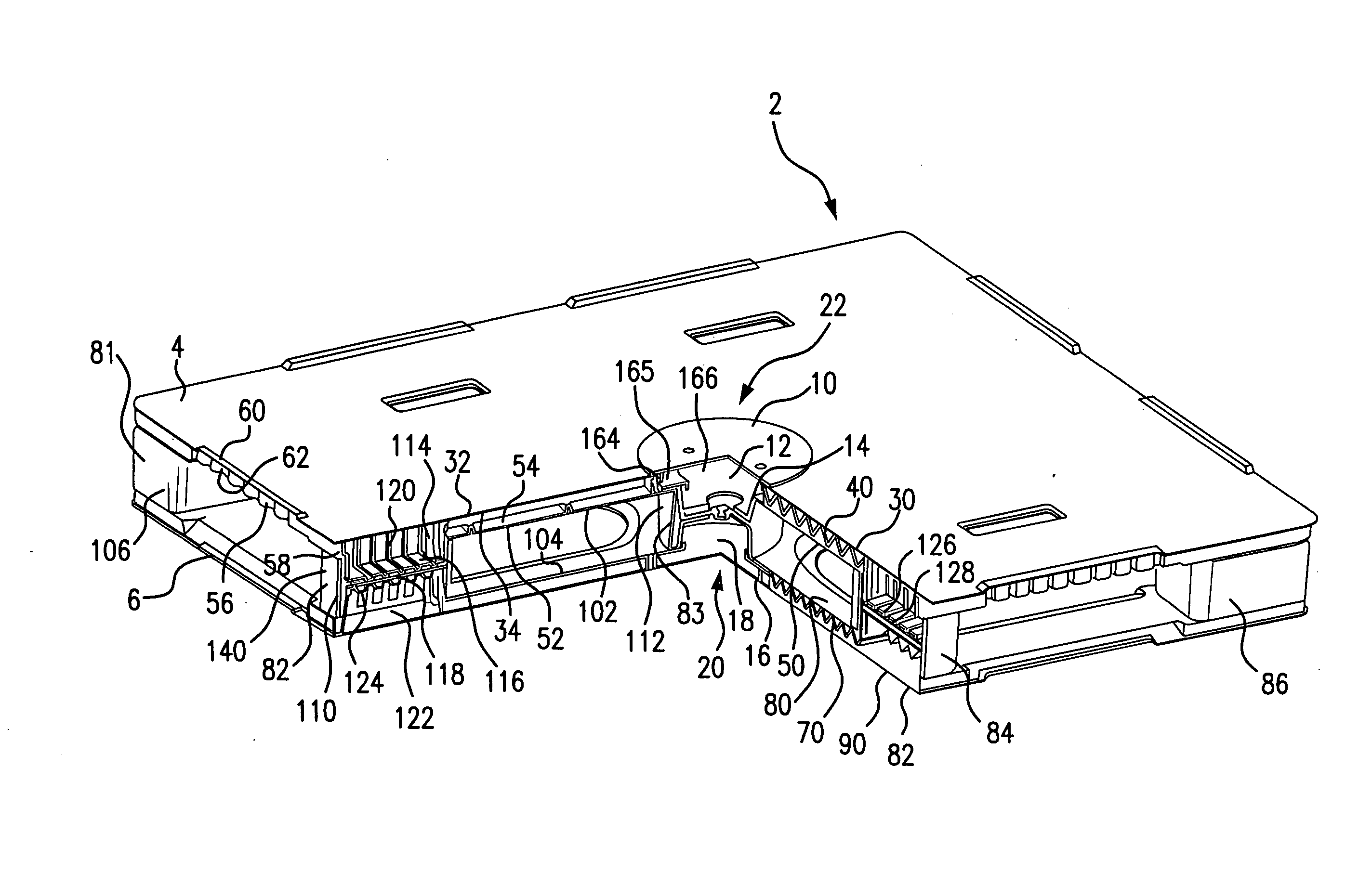
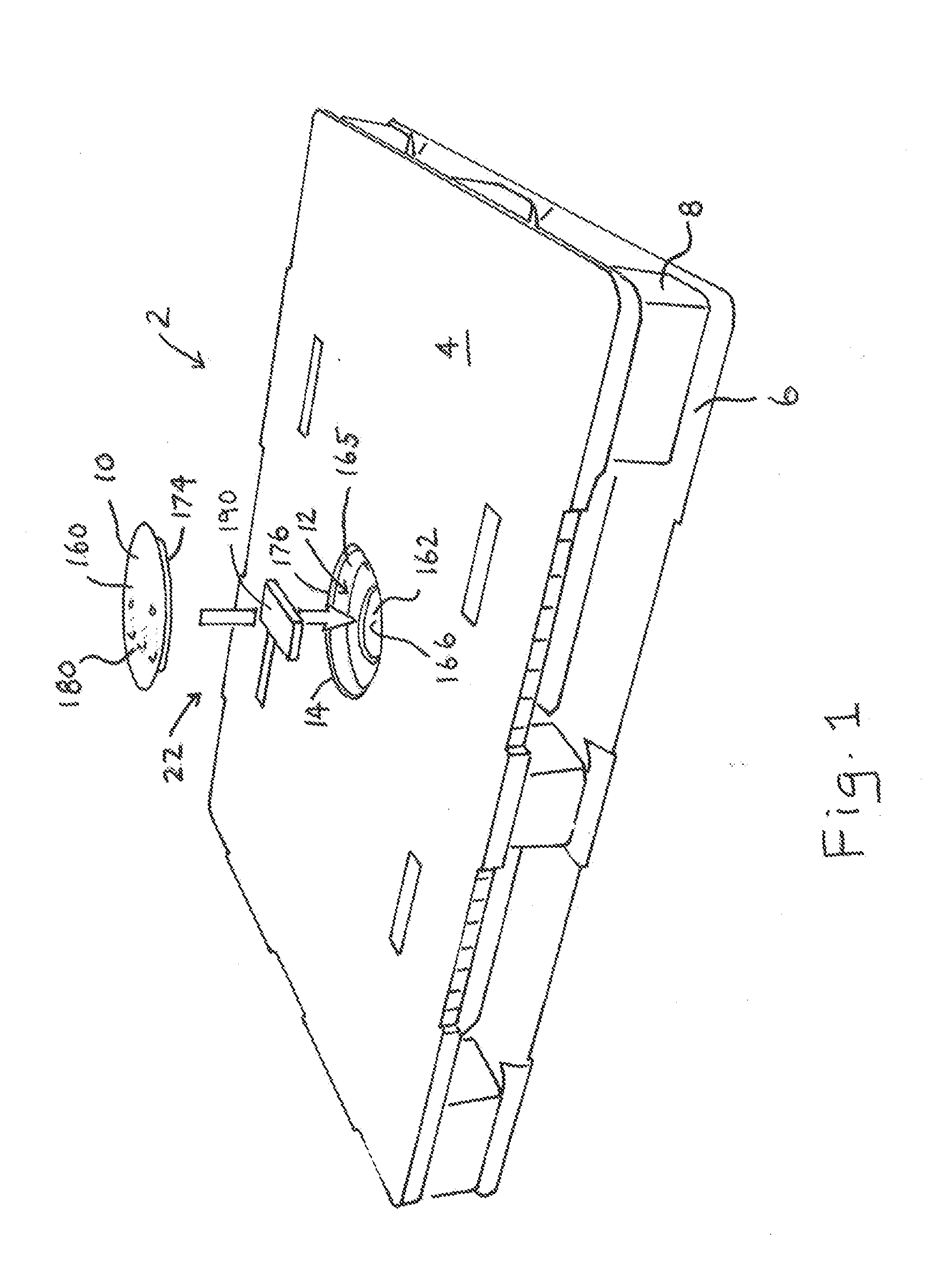
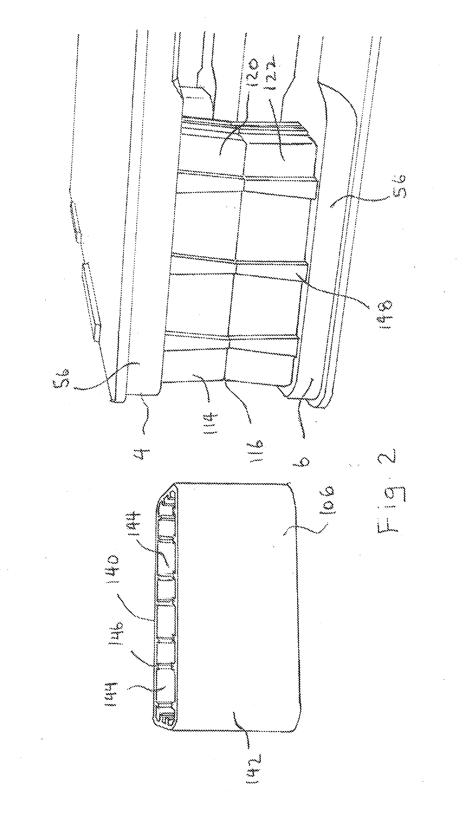
[0033]A preferred pallet 2 is shown in FIG. 1. The pallet includes a deck 4, a base 6 and nine impact resistant foot guards 8. Also shown is a first removable cover 10 for a first compartment 12 located within a center foot structure 14 of the deck. A corresponding second removable cover 16 for a second compartment 18 located with a center foot structure 20 of the base described. It should be appreciated that the position for the compartments and covers are not limited to the center foot assembly 22 of the pallet. The pallet comprises thirteen parts that are assembled into the pallet illustrated in FIG. 1. The pallet is a 48×40 inch rackable pallet, although many different pallet footprints, sizes and shapes are contemplated for pallets.

The Deck

[0034]The deck is made from three sheets of thermoplastic material that are thermoformed according to the triple sheet method. Each sheet is engineered to meet specific performance criteria. The top sheet 30 is a co-extruded product comprisin...


PUM


Abstract

A pallet structure that resists damage sustained by prior art pallets in pooled pallet distribution is disclosed. The pallet comprises a deck and a base separated by opposed block structures spaced to accommodate fork tines, pallet jacks and other pallet moving equipment. The block structures are inset from the boundary established by the outer dimensions of the pallet. Impact guards are provided to protect the block structures against impacts that could pierce the walls of the block structures allowing foreign materials to enter an interior space of the deck, base or block structure. The impact guards surround the block structures preventing impacts from all sides. The exterior surfaces of the impact guards, at the four pallet corners, form a continuous vertical wall which extends from the top of the deck to bottom of the base. Other new and useful improvements and advancements are described.

Description

FIELD OF THE INVENTION[0001]This invention relates to material handling pallets, and in particular to a newly invented plastic pallet having superior longevity compared to existing wood and prior art plastic pallets.BACKGROUND OF THE INVENTION[0002]Pallets of all description are in one way or another involved in the supply chains and logistic channels that deliver the vast majority of all products that are relied upon by society to exist. Wood pallets of many dimensions have been used in North America since after WWII due to the abundance and low cost of wood. The largest user groups of wood pallets over time have established standard pallet dimensions for each of their respective industry logistic networks. The largest user group of pallets in North America established a 48×40 inch pallet dimension standard may years ago, so that today most pallet loads delivered to distribution centers and supermarket stores use a 48×40 inch pallet. So many 48×40 inch wood pallets are used by indu...

Claims


Application Information

Patent Timeline
IPC IPC(8): B65D19/18B65D19/38
CPCB65D19/18B65D19/38B65D2519/00034B65D2519/00452B65D2519/00796B65D2519/00567B65D2519/00288B65D2519/00069B65D19/0012B65D2203/10B65D2519/00044B65D2519/00079B65D2519/00273B65D2519/00343B65D2519/00388B65D2519/00432B65D2519/00437B65D2519/00442B65D2519/00815
Inventor MUIRHEAD, SCOTT A.W.
Owner NEXTREME
Why Eureka
Try Eureka