
Material for Dissipating Heat From and/or Reducing Heat Signature of Electronic Devices and Clothing

a technology for electronic devices and materials, applied in the direction of protective garments, synthetic resin layered products, furniture parts, etc., can solve the problems of excessive heating, damage to electronic devices, discomfort or burns,

Inactive Publication Date: 2016-04-21
LAT ENTERPRISES
View PDF6 Cites 28 Cited by
  • Summary
  • Abstract
  • Description
  • Claims
  • Application Information

AI Technical Summary

Benefits of technology

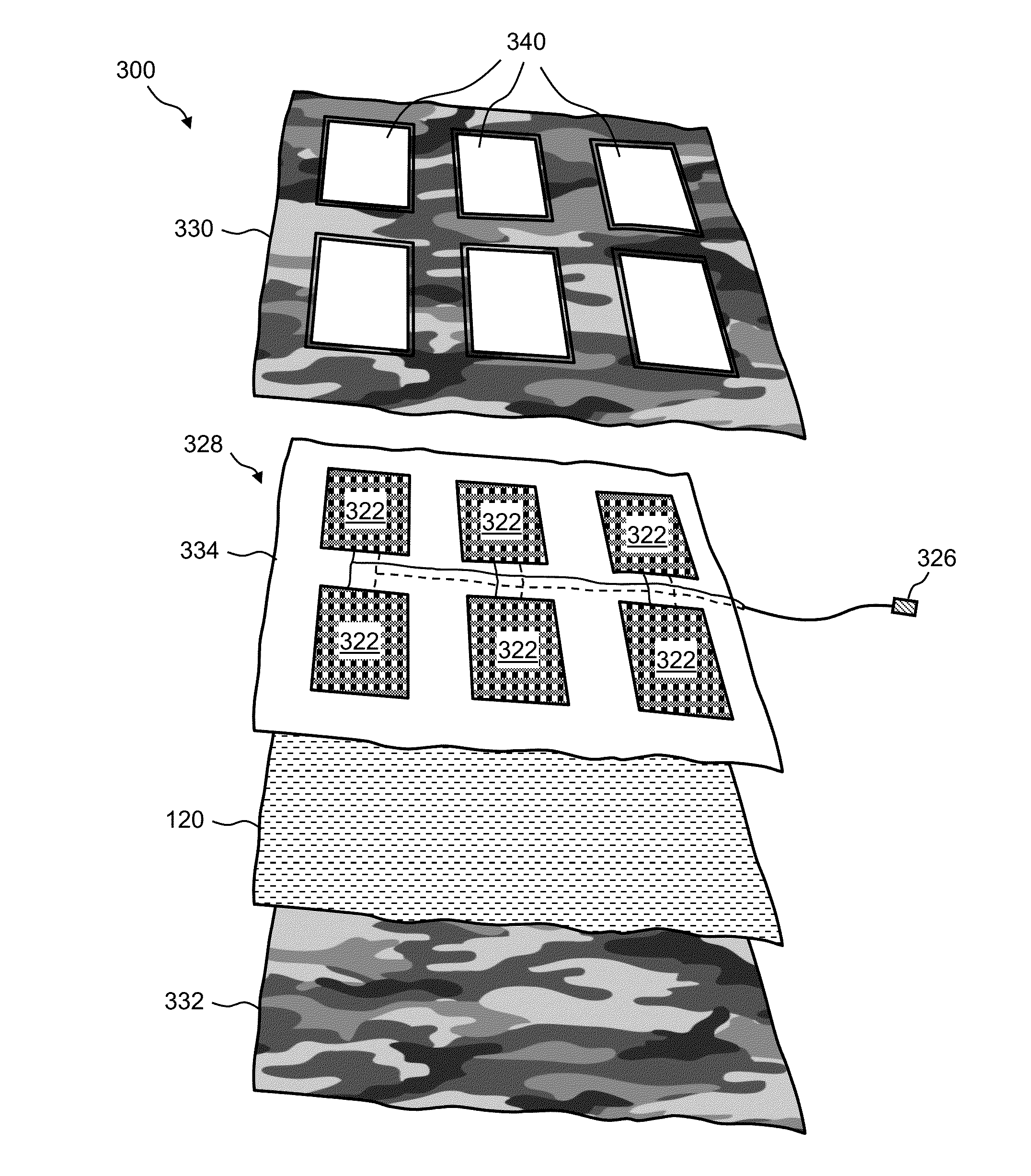
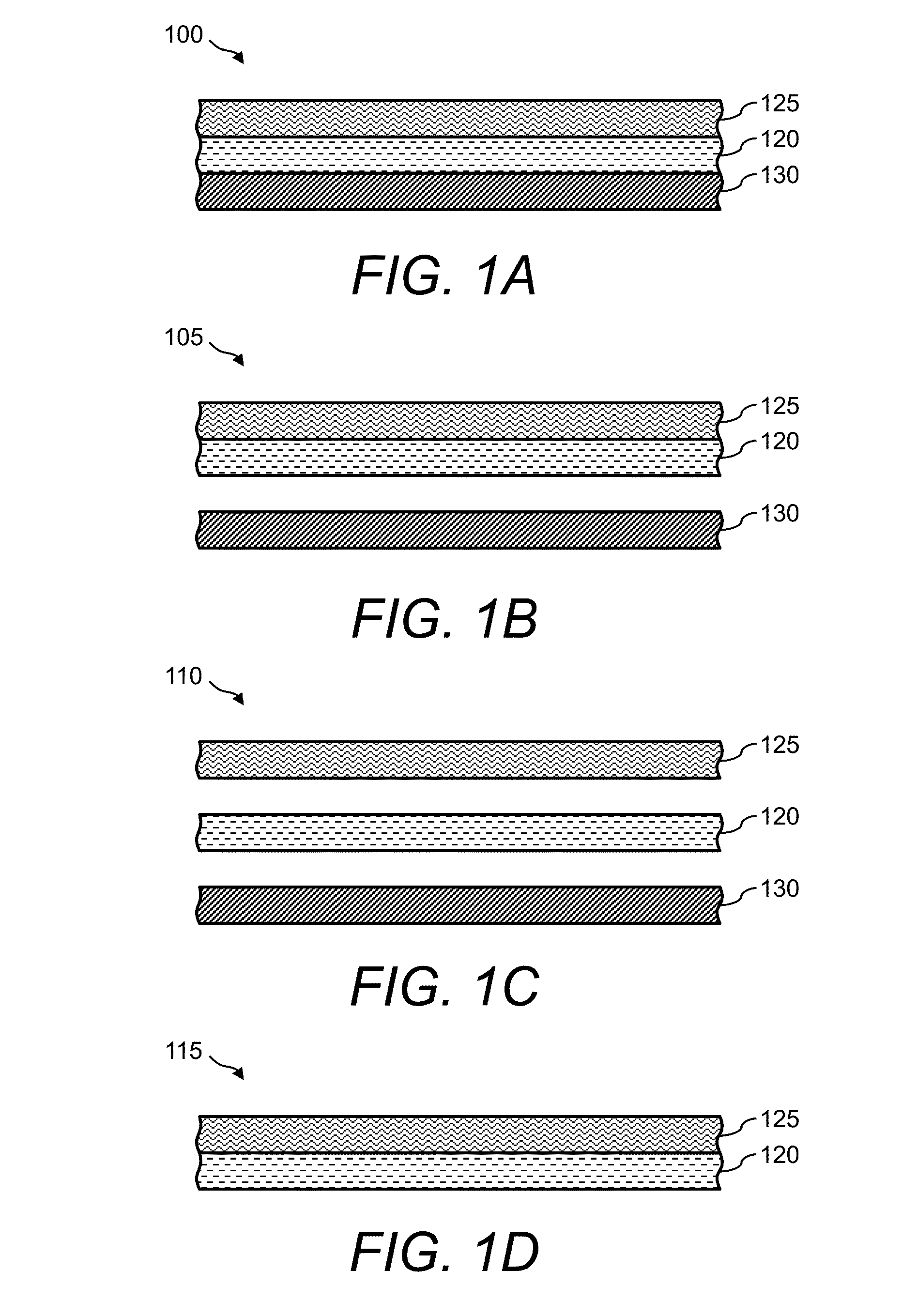
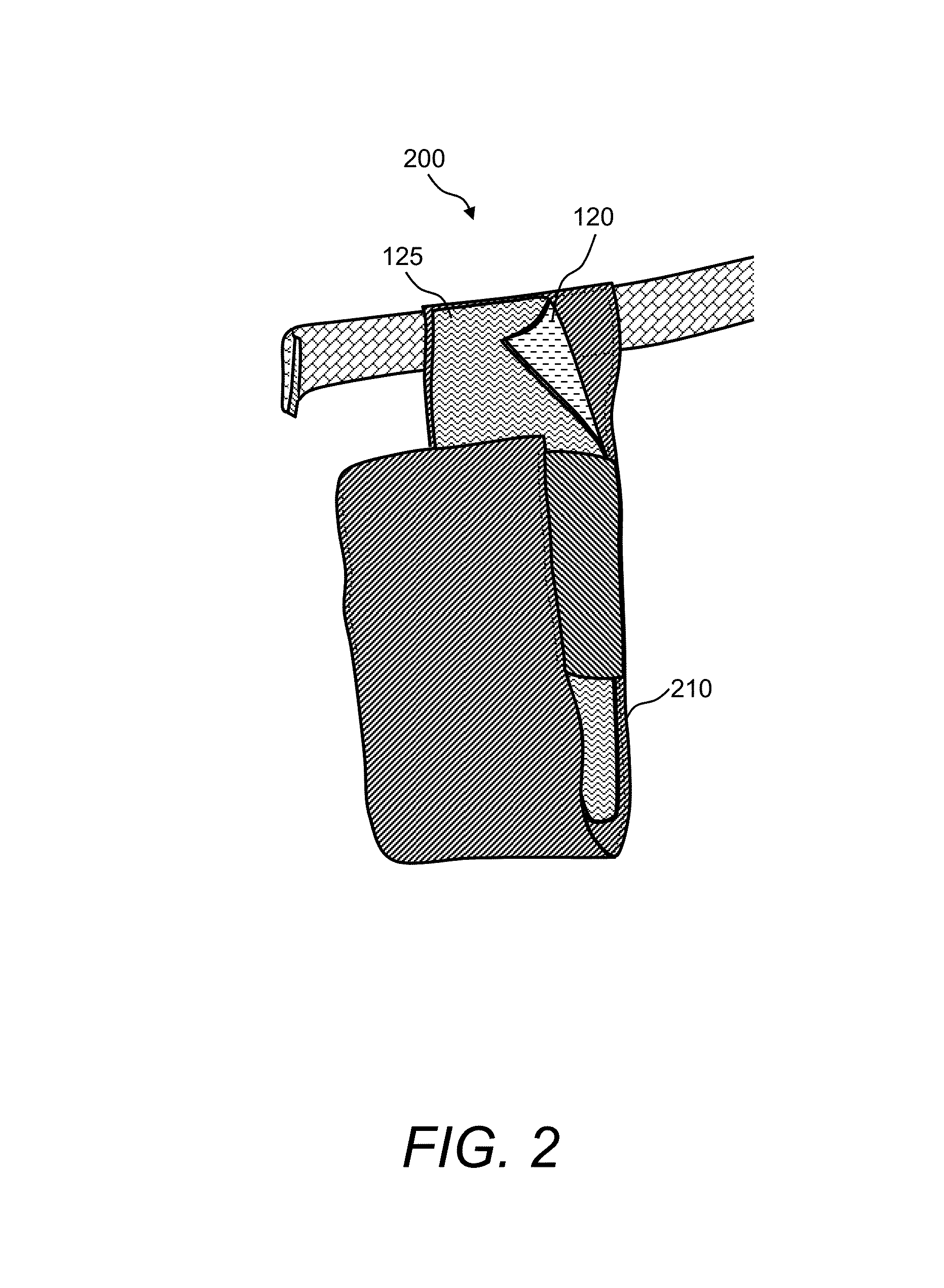
The present patent aims to provide an article for dissipating heat by using a heat-dissipating layer and one or more substrates closely related to the layer. The heat-dissipating layer can be made of various materials such as anti-static, anti-corrosion, or anti-tarnish materials like copper shielding plastic or copper impregnated polymer. The substrates can be flexible or rigid, such as fabric, glass, plastic, or metal, and can be bonded or loosely arranged with the heat-dissipating layer. The article can be used in applications such as a hand-held radio holder or a solar panel assembly. The technical effects of the invention include improved heat dissipation and protection against static, radio frequency, electromagnetic interference, corrosion, and tarnish, among others.

Problems solved by technology

In particular, a malfunctioning device can cause excessive heating.
A drawback of heat-generating devices is that the heat may be transferred to the person using or carrying the device, causing uncomfortableness or burns.
Another drawback of heat-generating devices is that the heat may be transferred to other devices, causing damage to these devices.
Further, in military applications, heat-generating devices may increase the heat signature of military personnel, making them more prone to detection by thermal imaging and therefore more prone to danger.

Method used


Image

  • Material for Dissipating Heat From and/or Reducing Heat Signature of Electronic Devices and Clothing
  • Material for Dissipating Heat From and/or Reducing Heat Signature of Electronic Devices and Clothing
  • Material for Dissipating Heat From and/or Reducing Heat Signature of Electronic Devices and Clothing

Examples


Embodiment Construction

[0013]The presently disclosed subject matter now will be described more fully hereinafter with reference to the accompanying Drawings, in which some, but not all embodiments of the presently disclosed subject matter are shown. Like numbers refer to like elements throughout. The presently disclosed subject matter may be embodied in many different forms and should not be construed as limited to the embodiments set forth herein; rather, these embodiments are provided so that this disclosure will satisfy applicable legal requirements. Indeed, many modifications and other embodiments of the presently disclosed subject matter set forth herein will come to mind to one skilled in the art to which the presently disclosed subject matter pertains having the benefit of the teachings presented in the foregoing descriptions and the associated Drawings. Therefore, it is to be understood that the presently disclosed subject matter is not to be limited to the specific embodiments disclosed and that ...


PUM

PropertyMeasurementUnit
Structureaaaaaaaaaa
Flexibilityaaaaaaaaaa
Frequencyaaaaaaaaaa

Abstract

A material for dissipating heat from and / or reducing the heat signature of electronic devices and clothing is disclosed. In one example, a heat-dissipating and / or heat signature-reducing layer is sandwiched between two substrates, wherein the substrates may be flexible, rigid, or a combination of both flexible and rigid. Further, examples of the heat-dissipating and / or heat signature-reducing layer include anti-static, anti-radio frequency (RF), anti-electromagnetic interference (EMI), anti-tarnish, and / or anti-corrosion materials.

Description

TECHNICAL FIELD[0001]The presently disclosed subject matter relates generally to methods of dissipating heat and / or managing heat signatures of objects and more particularly to a material for dissipating heat from and / or reducing the heat signature of electronic devices and / or clothing.BACKGROUND[0002]The military uses various types of portable electronic devices, such as portable battery-operated radios. Certain electronic devices may be heat-generating devices. In particular, a malfunctioning device can cause excessive heating. A drawback of heat-generating devices is that the heat may be transferred to the person using or carrying the device, causing uncomfortableness or burns. Another drawback of heat-generating devices is that the heat may be transferred to other devices, causing damage to these devices. Further, in military applications, heat-generating devices may increase the heat signature of military personnel, making them more prone to detection by thermal imaging and the...

Claims


Application Information

Patent Timeline
IPC IPC(8): H02S40/42
CPCH02S40/42H01L31/048H02S30/20Y02E10/50B32B5/06B32B5/16B32B5/26B32B5/30B32B15/14B32B15/16B32B27/12B32B27/14B32B27/302B32B27/32B32B3/08B32B2250/02B32B2250/03B32B2250/04B32B2250/40B32B2260/025B32B2260/046B32B2262/0261B32B2262/0276B32B2262/062B32B2264/105B32B2307/21B32B2307/30B32B2307/308B32B2307/536B32B2307/546B32B2307/714B32B2307/718B32B2307/7265B32B2307/732B32B2307/75B32B2437/02B32B2457/00B32B2457/12B32B2571/02B32B2307/212B32B2535/00B32B2437/00B32B5/02B32B2457/10B32B7/12B32B15/082B32B7/022B32B2479/00B32B2605/00B32B2571/00B32B7/09B32B27/08B32B15/043B32B15/085B32B27/06B32B17/06
Inventor THIEL, LAURACID, CARLOS
Owner LAT ENTERPRISES
Learn More