Eureka AIR delivers breakthrough ideas for toughest innovation challenges, trusted by R&D personnel around the world.

Isolated Power Networks Within An All-Electric LNG Plant And Methods For Operating Same

a technology of isolated power networks and all-electric lng plants, applied in the direction of positive displacement liquid engines, pumping, lighting and heating apparatus, etc., can solve the problems of shutting down the whole plant (all trains), redundancy of refrigeration compression, adversely affecting the entire plan

Active Publication Date: 2016-04-21
KELLOGG BROWN & ROOT LLC
View PDF26 Cites 5 Cited by
  • Summary
  • Abstract
  • Description
  • Claims
  • Application Information

AI Technical Summary

Benefits of technology

The patent text describes a system for generating and distributing electrical power in a liquefied natural gas (LNG) liquefaction plant. The system uses a motor driven compressor (MDC) power network that is electrically isolated from the balance of plant (BOP) power network. This means that any failure of a compressor or driver in the MDG or BOP power networks will not shut down the entire plant. The system also includes multiple liquefaction trains that can be operated at different power levels to optimize fuel efficiency and decrease emissions. The technical effect of this system is to increase redundancy and efficiency in the generation and distribution of electrical power, reducing the impact of failures or fluctuations in power requirements on the overall plant.

Problems solved by technology

In both the conventional gas turbine compressor and all-electric plant designs a single failure of any one compressor or driver (gas turbine or electric motor) will shut down its entire train, so neither has redundancy for refrigeration compression.
In both designs a failure of the single electrical network, which often includes multiple electric generators, will shut down the whole plant (all trains).
However, any kind of electric fault in a single train, a single generator, the BOP, or the electric utility grid can still adversely affect the entire plant because they are interconnected in a single network.
Consequently, operation of gas turbines at lower fuel rates will generally reduce efficiency and increase emissions, such as greenhouse gases including carbon dioxide and nitrogen oxides (e.g., NO.).
Such inefficiencies are indicative to increased greenhouse gas emissions by the gas turbine.

Method used


Image

  • Isolated Power Networks Within An All-Electric LNG Plant And Methods For Operating Same
  • Isolated Power Networks Within An All-Electric LNG Plant And Methods For Operating Same
  • Isolated Power Networks Within An All-Electric LNG Plant And Methods For Operating Same

Examples


Embodiment Construction

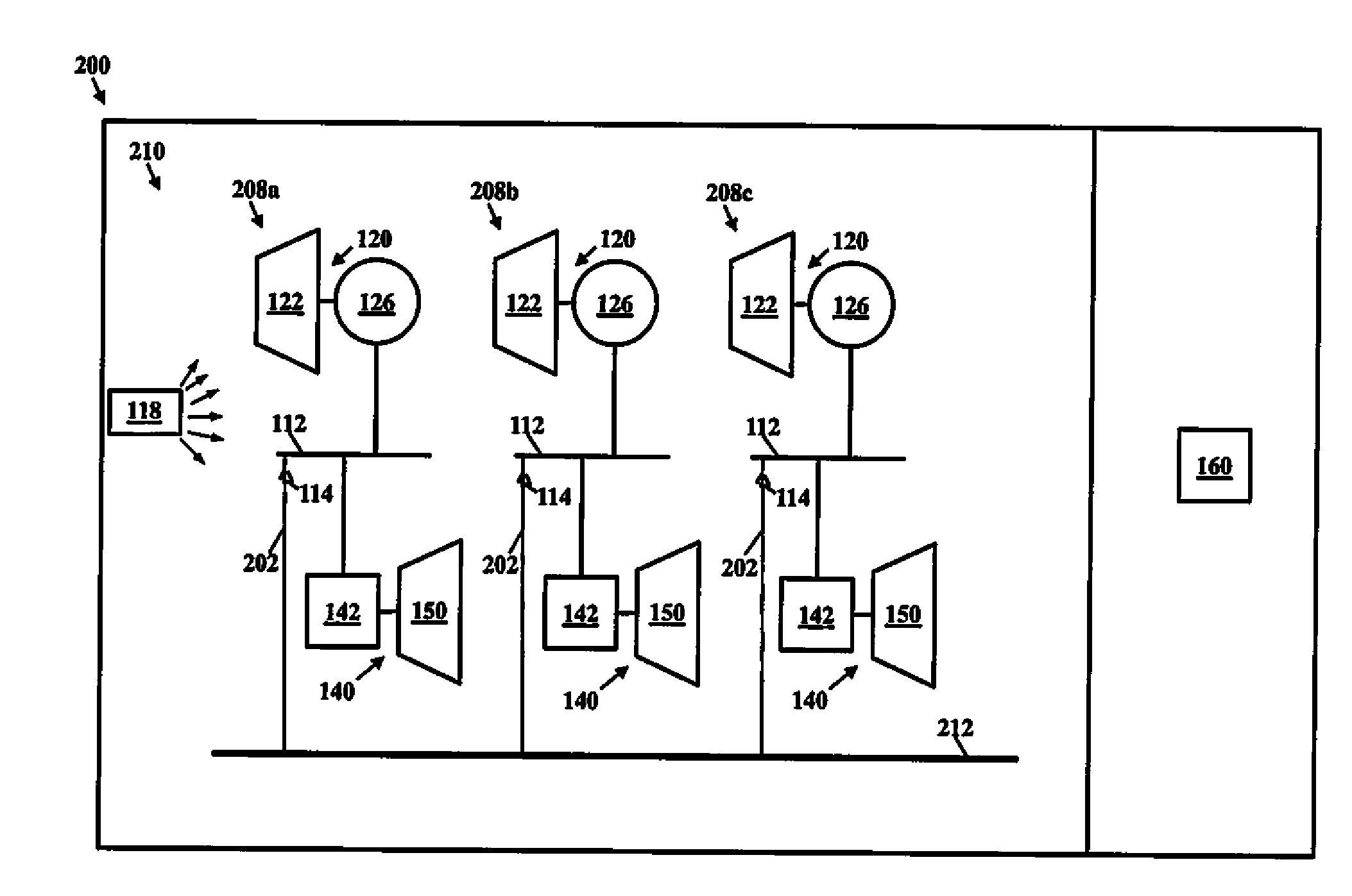
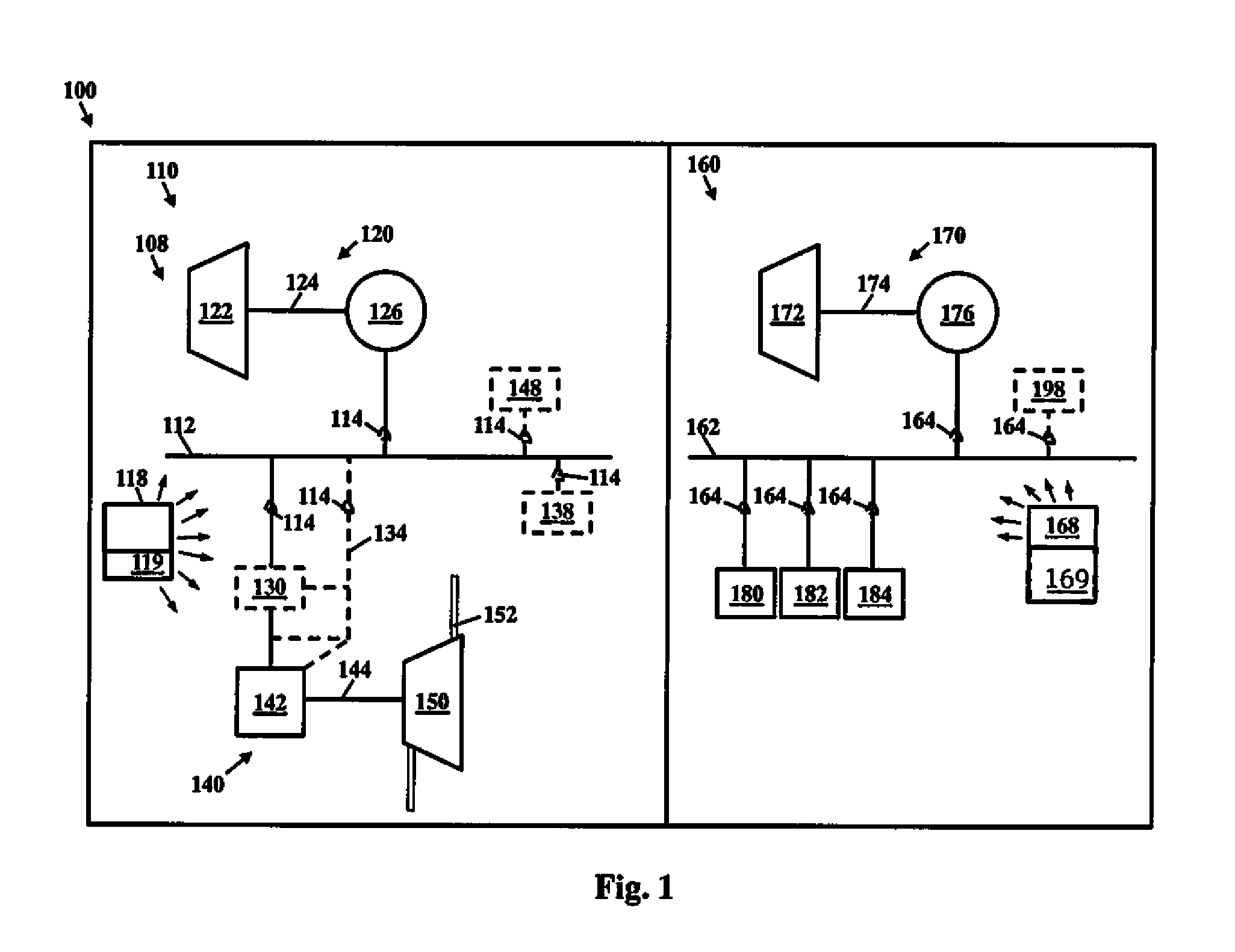
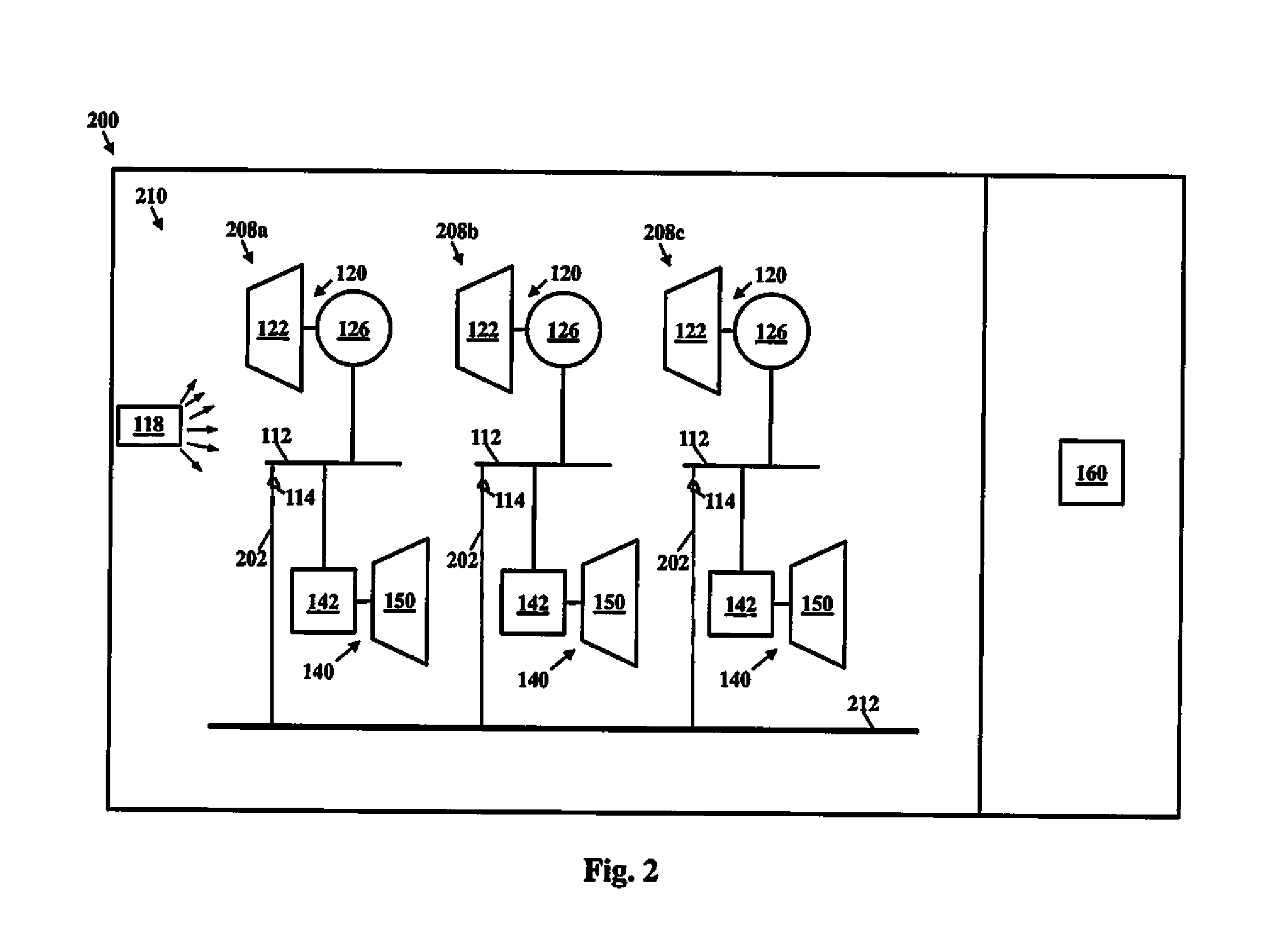
[0014]In one or more embodiments, an electrical power network can include a motor driven compressor (MDC) power network electrically isolated from a balance of plant (BOP) power network. The MDC power network can be configured to generate and distribute MDC electrical power and the BOP power network can be configured to generate and distribute BOP electrical power. The MDC power network can include one or more MDC trains, and each of the MDC trains can include an MDC distribution bus, one or more MDC turbine generators, one or more electric motors, and one or more compressors. The one or more MDC turbine generators can be configured to generate the MDC electrical power. The MDC distribution bus can be configured to distribute the MDC electrical power and can be electrically connected to the one or more MDC turbine generators and the one or more electric motors. Each of the compressors can be coupled to an electric motor and can be configured to be driven by the electric motor. In ce...


PUM


Abstract

Embodiments generally relate to a motor driven compressor (MDC) power network electrically isolated and independent from a balance of plant (BOP) power network within an electrical power system and methods for operating the same. In one embodiment, the MDC power network can include one or more MDC trains, and each of the MDC trains can include an MDC distribution bus, one or more MDC turbine generators, one or more electric motors, and one or more compressors. The BOP power network can include a BOP distribution bus, one or more BOP turbine generators, and one or more plant circuits comprising the balance of the plant.

Description

BACKGROUND[0001]1. Field[0002]Embodiments described generally relate to systems and methods for generating and distributing electricity within a process plant. More particularly, embodiments relate to one or more motor driven compressor (MDC) power networks for an “all-electric” liquefied natural gas (LNG) liquefaction plant, each driving a separate process line or train, electrically isolated and independent from each other and from the balance-of-the-plant (BOP) power network, and methods for operating same.[0003]2. Description of the Related Art[0004]In the production of LNG and other liquefied gases and fluids, refrigeration compressors are often driven by gas turbines, steam turbines, or connected to other driver systems by belts or shafts. Multiple compressors acting together on the same process stream comprise a single processtrain”, in which a fault in, or required maintenance of, any one compressor or driver will shut down the entire process train. An LNG liquefaction pla...

Claims


Application Information

Patent Timeline
Patent Type & Authority Applications(United States)
IPC IPC(8): F25J1/02F04B17/03F25J1/00H02J3/00
CPCF25J1/0284F25J1/0022F04B17/03H02J3/00F04D25/06F04D25/16F25J1/0269F25J1/0298F25J2240/80H02J3/30Y02E60/16
Inventor MCCARTHY, KEITH
Owner KELLOGG BROWN & ROOT LLC
Why Eureka
Eureka Blog
Learn More