Tool tongs

a technology of tongs and tools, applied in the field of pairing, to achieve the effect of high weight and laborious manufactur

Active Publication Date: 2016-04-14
GROB WERKE & K G
View PDF7 Cites 2 Cited by
  • Summary
  • Abstract
  • Description
  • Claims
  • Application Information

AI Technical Summary

Benefits of technology

[0009]Referring to this state of the art, it is an object of the invention to remove at least one of the disadvantages of the state of the art, such as, for example, laborious manufacture and high weight.
[0010]The problem of the invention is solved by tool tongs for the releasable holding of a tool that is provided in a machine tool, wherein the tool tongs are formed by a tongs basic element and a tongs clamping element interacting with and connected to the tongs basic element, wherein in the tool holding position the tongs basic element and the tongs clamping element hold the tool clampingly on gripping elements of the tool, wherein the tongs basic element and / or the tongs clamping element is / are made from an inherently elastic flat or plate-like material, such as, for example, steel sheet, wherein the tongs clamping element is put on the tongs basic element and is fastened there, and wherein an elastic deformation of the tongs clamping element is provided for releasing or clamping of the tool. This configuration according to the invention allows now forming the basic element and the tongs clamping element of flat material or plate-like material instead of the cast components used so far. Thus, in a single way both tongs elements can be manufactured. In contrast to the so far laborious casting procedures, what is required now is only severing or cutting the two elements out of the plate-like material, such as, for example steel sheet. This can be performed by simple and conventional machining processes. The effort for machining is reduced considerably. Furthermore, also the material used is also reduced considerably altogether, so that the weight of the tool tongs according to the invention is clearly lower. The manufacture can also be realized with, for example, CNC-controlled machines in a clearly shorter time than this has used to be the rule so far for the tongs elements, namely the tongs basic element and the tongs clamping element. Furthermore, even the pressure spring, required so far in the state of the art, is saved as the plate-like flat material shows a certain inherent elasticity, so that the spring is not necessary anymore either.
[0011]It is an advantage when the tool tongs according to the invention is characterized in that the tongs clamping element is made of inherent-elastic material, for example spring steel. The design of the tongs clamping element of spring steel makes, of course, the entire tool tongs altogether even essentially more flexible, and, in particular, the inherent spring force of the material leads to the effect that the additional spring at the tool tongs is not required anymore. The two tongs elements, that is tongs basic element and tongs clamping element, rest planely one upon the other. The tongs clamping element is fixed at least only on one spot or one point of the basic element, so that, because of the spring power, the tongs clamping element is easily resilient because of its inherent elasticity. Thus, when pressurized, the tongs can open at the end facing the tool, and, when released, close again. A complicated, seesaw-like axis connecting the two tongs elements is not necessary anymore either.

Problems solved by technology

In contrast to the so far laborious casting procedures, what is required now is only severing or cutting the two elements out of the plate-like material, such as, for example steel sheet.

Method used


Image

  • Tool tongs
  • Tool tongs
  • Tool tongs

Examples


Embodiment Construction

[0045]In the figures, identical or corresponding elements are indicated each time by the same reference numbers, and therefore are, if not different, not described anew.

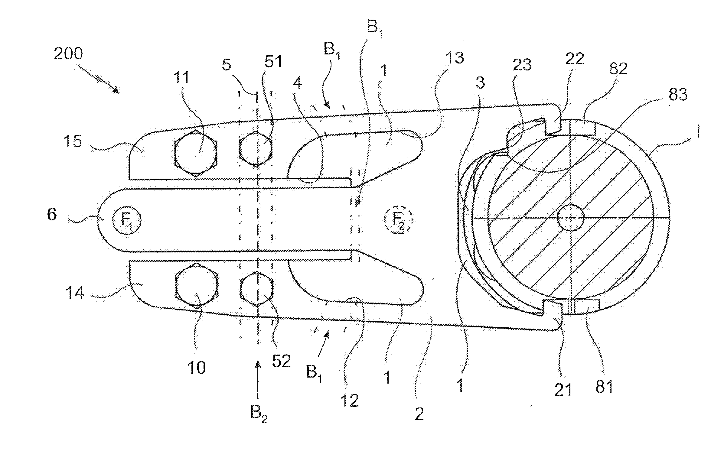
[0046]FIGS. 1a to 1c show different views of an embodiment of a tool tongs I according to the invention. As FIGS. 1a to 1c all refer to the same embodiment, they will also be described together in the following. FIG. 1a shows here a three-dimensional presentation of the tool tongs 200 according to the invention. As it can be seen, a tongs basic element 1 is provided on which a tongs clamping element 2 is fastened by, for example, the screws referred to as attachment spots 51, 52. By means of these screws 51, 52, the tongs clamping element 2, which is formed of inherent elastic material, is fixed at the tongs basic element 1. The tongs basic element 1 is, as it can be seen, provided with a U-shaped recess 4, so that on the outside two lateral webs 14, 15 are created on which the tongs clamping element 2 is put on and ...


PUM


Abstract

The invention relates to tool tongs for the releasable holding of a tool, for example in a machine tool. The invention is characterized in that the tool tongs are formed by a tongs basic element and a tongs clamping element interacting and connected with the tongs basic element, wherein in the tool holding position the tongs basic element and the tongs clamping element hold the tool clampingly at its gripping elements, wherein the tongs basic element and / or the tongs clamping element is / are formed of flat material or plate-like material, such as, for example, steel sheet or the like.

Description

CROSS REFERENCE TO RELATED APPLICATIONS[0001]This application is a divisional application of U.S. patent application Ser. No. 13 / 837,264 filed Mar. 15, 2013, which claims priority from German Patent Application No. 10 2012 102 263.1 filed on Mar. 16, 2012 and German Patent Application No. 10 2012 104 733.2 filed May 31, 2012, which are hereby incorporated by reference.FIELD OF INVENTION[0002]The invention refers to a pair of tool tongs provided for the releasable holding of a tool, for example in a machine tool.BACKGROUND OF THE INVENTION[0003]Tool tongs of this kind are known. They are known either individually or in the form of tool changers in machining tools or machining lines. Here, machining tools of a machine tool supplied in a tool supply are transported into the machining spindle or removed from it. These processes are executed completely automatically, that is without manual interaction of a worker. It is known in the state of the art to form tool tongs of this kind from a...

Claims


Application Information

Patent Timeline
Patent Type & Authority Applications(United States)
IPC IPC(8): B23Q3/155
CPCB23Q3/15553B23Q3/15526B23Q7/043B23Q2003/15527Y10S483/902Y10T483/17Y10T483/1795Y10T483/1809Y10T483/1882B25B7/02B25B9/00B23Q3/15706B23Q3/15766B25J11/00B25J15/12B23Q3/15722
Inventor GROB, H. C. BURKHART
Owner GROB WERKE & K G
Why Eureka
Try Eureka