
Vacuum cleaner pneumatically connected to a power tool, method for controlling operation parameters of such a vacuum cleaner and power tool for pneumatic connection to such a vacuum cleaner

a vacuum cleaner and power tool technology, applied in the field of vacuum cleaners, can solve the problems of obstructing the free view of the user onto the working area, creating dust, and dust on the working surface of the workpiece,

Inactive Publication Date: 2016-04-14
VALENTINI GUIDO
View PDF6 Cites 42 Cited by
  • Summary
  • Abstract
  • Description
  • Claims
  • Application Information

AI Technical Summary

Benefits of technology

The vacuum cleaner described in the patent is designed to remove dust and debris from the working area between the tool and the surface being worked on. This prevents dust from getting in the tool and causing problems with its functioning. The vacuum cleaner can also identify the tool based on its unique characteristics, which can be stored in a database and used to adjust its operation parameters. The correction signals are determined based on the correlation between the received information and the dust concentration in the air. This allows the vacuum cleaner to comply with the regulations regarding dust in the air. Overall, the vacuum cleaner improves the working area by keeping it clean and safe for the user and helps to achieve better results with the tool.

Problems solved by technology

However, a fixed or static tool is usually stationary during its operation.
All these tools create dust the one way or the other during operation.
Dust on the working surface of the workpiece could impede or negatively affect proper working of the surface with the tool and its working element, respectively.
In particular, an excess amount of dust could obstruct a user's free view onto the working area and could impede proper functioning of the working element, for example if excess dust sticks to the working element, e.g. in the fibers or filaments of a polishing pad or on the abrasive surface of an abrasive sheet material.
An excess amount of dust in the air surrounding the tool or working area could lead to a dust concentration in the air exceeding approved maximum values and provoke negative health effects with the user of the tool and other people located near the operating tool.

Method used


Image

  • Vacuum cleaner pneumatically connected to a power tool, method for controlling operation parameters of such a vacuum cleaner and power tool for pneumatic connection to such a vacuum cleaner
  • Vacuum cleaner pneumatically connected to a power tool, method for controlling operation parameters of such a vacuum cleaner and power tool for pneumatic connection to such a vacuum cleaner
  • Vacuum cleaner pneumatically connected to a power tool, method for controlling operation parameters of such a vacuum cleaner and power tool for pneumatic connection to such a vacuum cleaner

Examples


Embodiment Construction

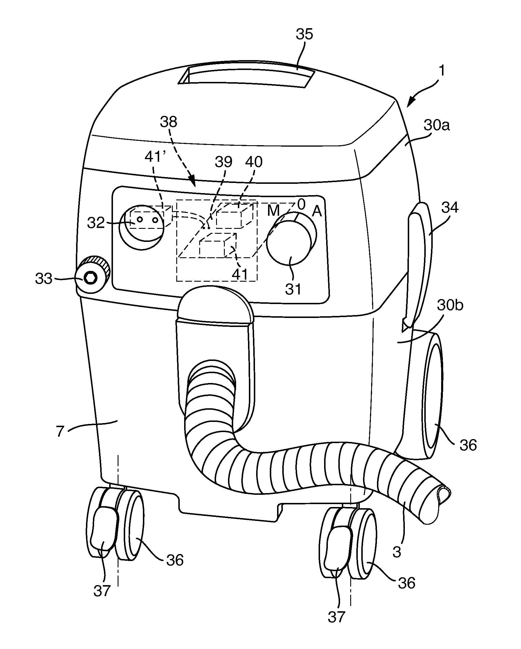
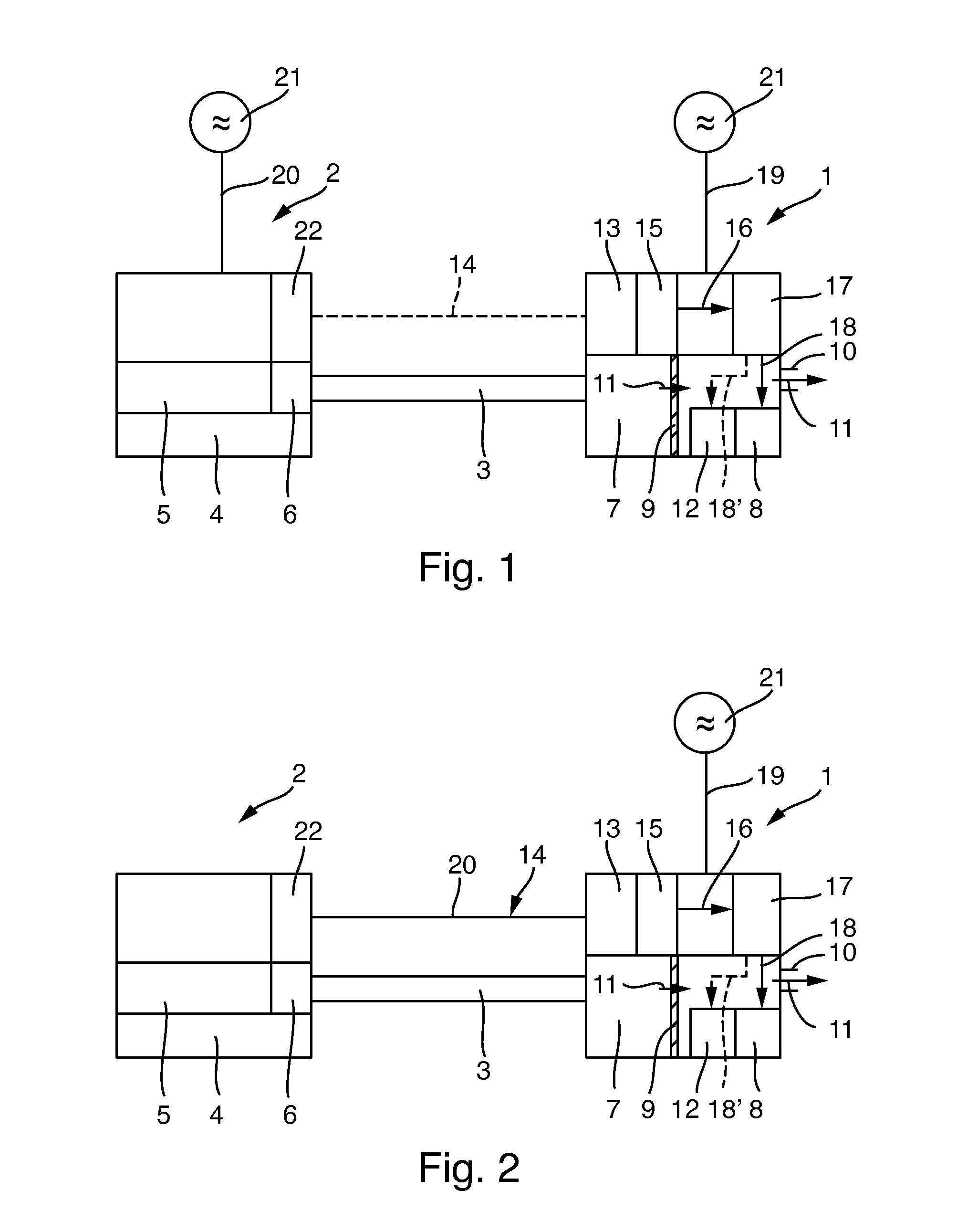
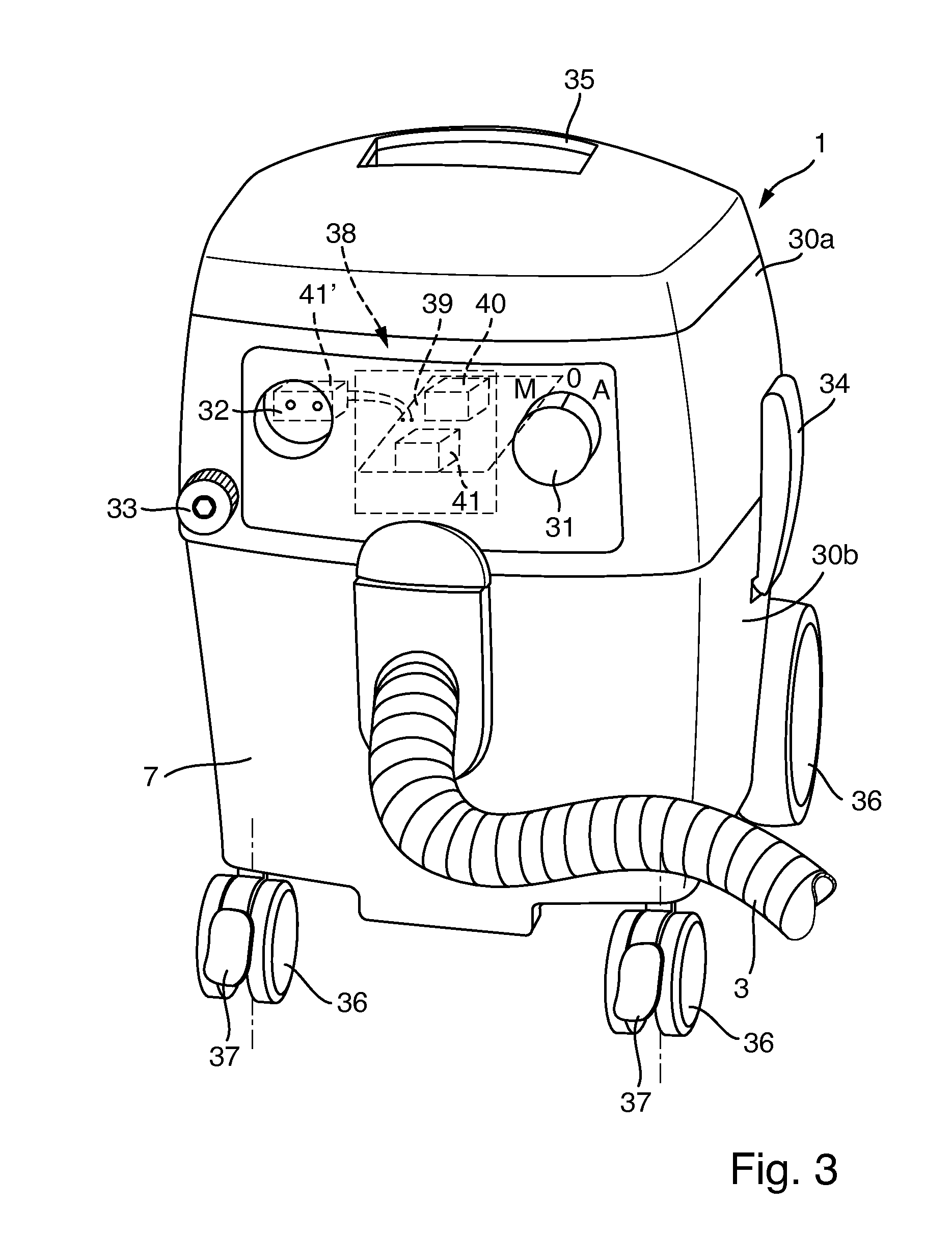
[0050]FIG. 1 shows a vacuum cleaner 1 pneumatically connected to a hand held or hand guided power tool 2 by a pneumatic tube or hose 3. Of course, the tool 2 could also be a stationary or fixed power tool. The tool 2 can be a sander, a polisher, a glazing machine, a grinder, a planer, a drill, a scouring machine, an electrical saw or any other machine tool generating dust during its operation. The tool 2 comprises a working element 4, which—depending on the type of tool 2—can be a supporting pad for receiving and holding abrasive sheet material (e.g. sanding paper or a sanding fabric). Furthermore, the working element 4 could comprise a drilling bit or a saw plate or the like. The tool 2 is adapted to work a working surface of a workpiece with the tool's working element 4, for example by grinding, sanding, polishing, glazing, scouring or sawing the surface. Furthermore, the tool 2 could be adapted to drill a hole in the surface and the workpiece. To this end, the working element 4 p...


PUM


Abstract

The present invention refers to a vacuum cleaner adapted for pneumatic connection to a power tool generating dust during its operation, in order to draw at least part of the dust away from the tool into the vacuum cleaner, the vacuum cleaner operating under certain operation parameters when it is turned on. In order to optimize operation of the vacuum cleaner based on the characteristics of the tool and / or its current use, the vacuum cleaner includes a reception mechanism for receiving information regarding characteristics of the tool and / or its current use, a processing and calculation mechanism for processing the received information and for calculating a correction signal for at least one of the vacuum cleaner's operation parameters based on the received information, and an adjustment mechanism for adjusting the at least one operation parameter based on the calculated correction signal.

Description

CROSS-REFERENCE TO RELATED APPLICATIONS[0001]The present application claims priority to and all the benefits of European Patent Application No. 14 188668.9-1712, filed on Oct. 13, 2014, which is hereby expressly incorporated herein by reference in its entirety.BACKGROUND OF THE INVENTION[0002]1. Field of the Invention[0003]The present invention is directed toward a vacuum cleaner adapted for pneumatic connection to a power tool generating dust during its operation. During operation of the tool at least part of the dust is drawn away from the tool into the vacuum cleaner. The vacuum cleaner operates under certain operation parameters when it is turned on, for example a certain speed of the vacuum cleaner's motor, a certain aspiration or suction performance, or a frequency of a cleaning process of the vacuum cleaner's filter.[0004]Furthermore, the invention refers to a method for controlling operation parameters under which a vacuum cleaner is operated if it is turned on. The vacuum c...

Claims


Application Information

Patent Timeline
IPC IPC(8): A47L7/00A47L9/20H02K7/14A47L9/28G08C17/02A47L5/12A47L9/00
CPCH02K7/145A47L7/0095A47L5/12G08C17/02A47L9/009A47L9/2821A47L9/20A47L7/00A47L9/28A47L9/281A47L9/2836A47L9/2868
Inventor VALENTINI, GUIDO
Owner VALENTINI GUIDO
Learn More