
Air compressor

a technology of air compressor and air compressor, which is applied in the direction of positive displacement liquid engine, piston pump, liquid fuel engine, etc., can solve the problems of wasteful generation, and achieve the effect of reducing maintenance requirements and operating costs of air compressors, and operating air compressors for a long tim

Active Publication Date: 2016-03-31
MAKITA CORP
View PDF7 Cites 5 Cited by
  • Summary
  • Abstract
  • Description
  • Claims
  • Application Information

AI Technical Summary

Benefits of technology

This patent describes a technique for reducing fuel consumption in an air compressor driven by an internal combustion engine. The engine stops when the air pressure inside the air-storage tank reaches a set pressure, resulting in zero fuel consumption during idle state. The set pressure can be modified to adjust the air compressor's operating efficiency based on usage conditions. The air compressor can also operate using motive power provided by an electric motor or the engine, depending on the air pressure inside the tank. By appropriately setting the timing of when the motive power is switched from electric to engine, air-generation efficiency can be maintained in different operating conditions while reducing fuel consumption. Additionally, the air compressor can operate for a long time without needing to recharge the battery, reducing maintenance requirements and operating costs.

Problems solved by technology

In the above-mentioned known air compressor, because the compressed air generated during an idling operation is not stored in the air-storage tank, it is wastefully generated from the standpoint that such compressed air is not used to drive the pneumatic tool.

Method used


Image

  • Air compressor
  • Air compressor
  • Air compressor

Examples


first embodiment

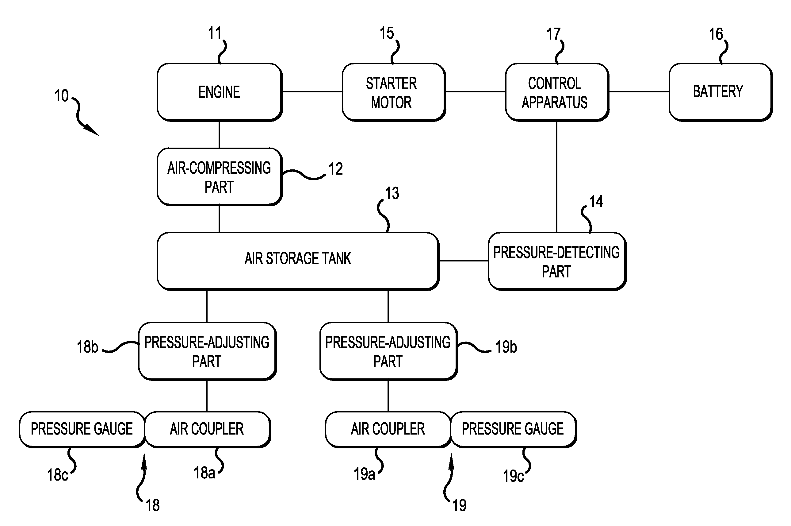
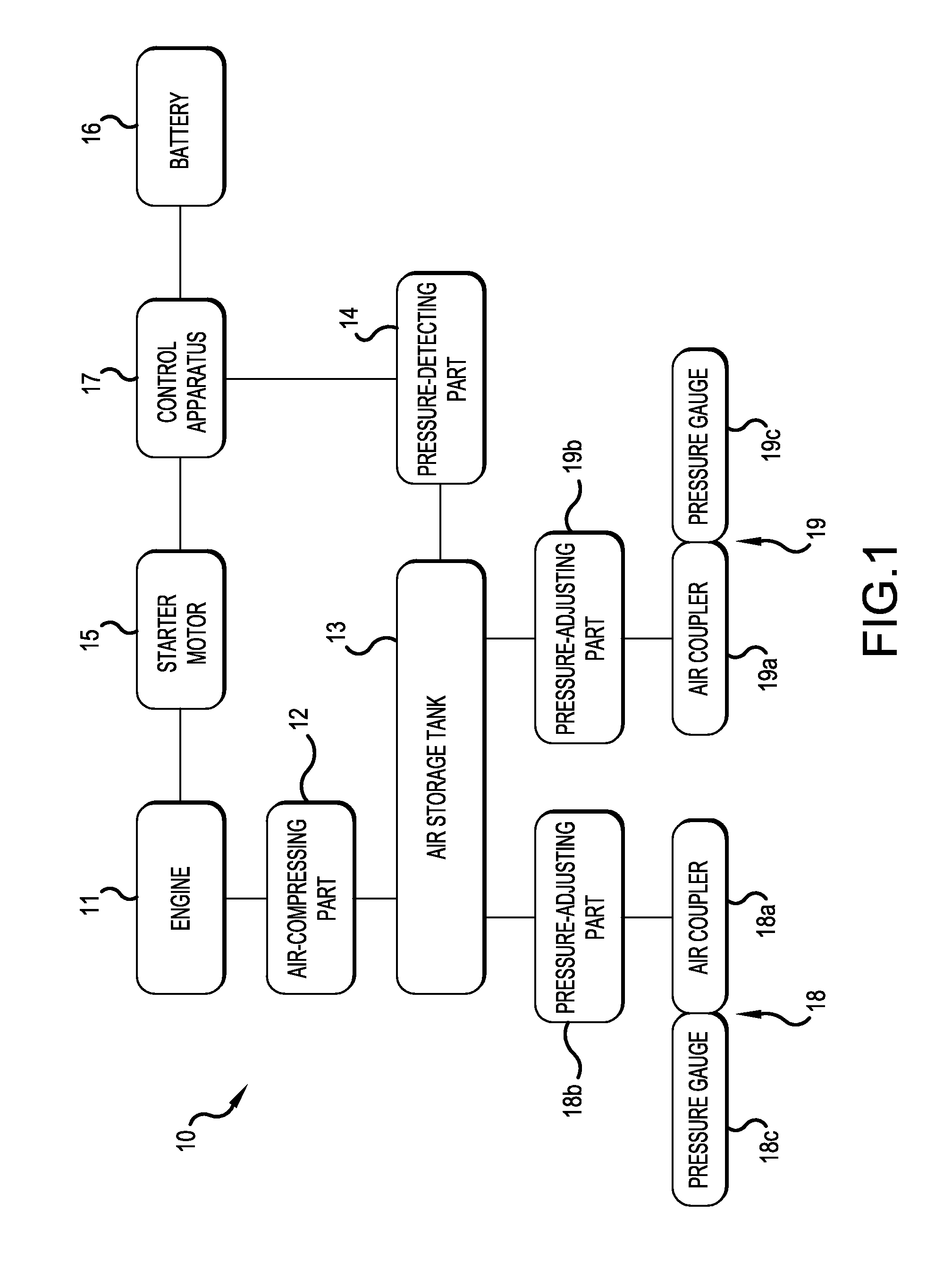
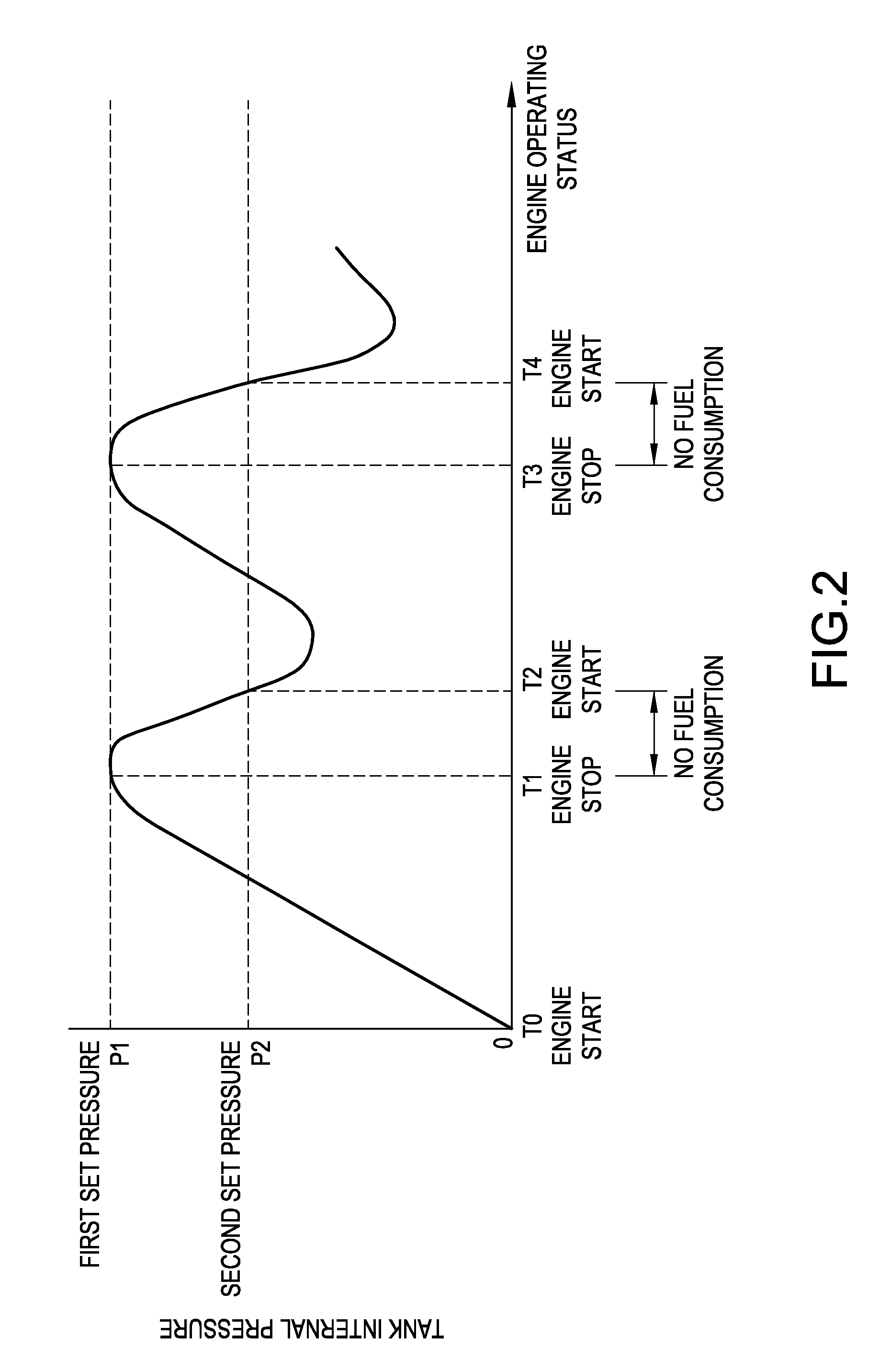
[0035]Thus, according to the air compressor 10 of the first embodiment, once the air pressure inside the air-storage tank 13 reaches the first set pressure P1, the engine 11 then remains in the stopped state (T1-T2, T3-T4), unless or until the air pressure decreases to the second set pressure P2. The engine 11 is stopped by cutting off the supply of the fuel. Consequently, unlike in the idling state of conventional air compressors, fuel consumption becomes zero, and therefore the fuel consumption (air-generation efficiency) of the air compressor 10 can be greatly improved.

[0036]The above-described first embodiment uses the engine 11 as its sole motive-power source for operating (driving) the air-compressing part 12. However, as will be described below, the air compressor 20 of the second embodiment of the present teachings shown in FIG. 3 has a two-way-drive-type motive-power source that comprises, in addition to the engine 11, an electric motor 21. Both of the engine 11 and the ele...

second embodiment

[0045]Thus, according to the air compressor 20 of the second embodiment, the air-compressing part 12 is operated using a two-system motive-power source, that is, it has both an engine drive and an electric motor drive. The air-compressing part 12 operates (is driven) using the electric motor 21 as the motive-power source in the low-pressure range below the third set pressure P3, and the air-compressing part 12 operates (is driven) using the engine 11 as the motive-power source only in the high-pressure range at or above the third set pressure P3. Therefore, no fuel is consumed during the operation states (T5-T6, T8-T9) of the air-compressing part 12 in the low-pressure range below the third set pressure P3 in addition to the stopped state of the air-compressing part 12, and thereby the overall fuel consumption of the engine 11 can be greatly reduced.

[0046]Various changes and modifications can be made to the above-described embodiments without departing from the scope or spirit of th...


PUM


Abstract

An air compressor includes an internal combustion engine for driving an air compressing part that generates compressed air, which is stored in an air-storage tank. At a point in time when the air pressure inside the air-storage tank has increased to a first set pressure, the supply of fuel to the engine is cut off, thereby stopping the engine and the combustion of fuel. At a point in time when the air pressure inside the air-storage tank has decreased from the first set pressure to a second set pressure, a starter motor is started up to resume the operation of the engine.

Description

CROSS-REFERENCE[0001]This application claims priority to Japanese patent application serial number 2014-198640, filed on Sep. 29, 2014, the contents of which are incorporated herein by reference in its entirety.TECHNICAL FIELD[0002]The present invention generally relates to an air compressor for generating compressed air that may be supplied to a pneumatic tool such as a nailer.BACKGROUND ART[0003]Some known air compressors operate using an internal combustion engine as its motive-power source. Such air compressors comprise, in addition to the engine, an air-compressing part, such as a piston that is reciprocally slidable inside a cylinder, an air-storage tank, which stores compressed air discharged from the cylinder, and a pressure-detecting means, which detects the air pressure inside the air-storage tank. Such air compressors are configured such that, at the point in time when the air pressure inside the air-storage tank has increased to a set pressure, the engine is switched to ...

Claims


Application Information

Patent Timeline
IPC IPC(8): F04B35/00F04B35/04F04B37/10F04B39/12F04B49/02F04B53/14
CPCF04B35/002F04B35/04F04B53/14F04B39/121F04B49/022F04B37/10F04B35/06F04B41/02F04B49/02F04B49/06F04C2240/45
Inventor NISHIDO, NORIYUKIMIYATA, KENICHI
Owner MAKITA CORP
Learn More