
Movable Ultraviolet Radiation Source

Active Publication Date: 2016-03-31
SENSOR ELECTRONICS TECH
View PDF2 Cites 49 Cited by
  • Summary
  • Abstract
  • Description
  • Claims
  • Application Information

AI Technical Summary

Benefits of technology

The invention aims to address certain problems and make improvements in existing technologies. The technical effects of this invention include solving difficult problems or making improvements in existing technologies.

Problems solved by technology

However, the inventors recognize that use of such optical elements can significantly reduce an overall efficiency of the system due to a generally large absorbance of ultraviolet radiation.
Other applications also may include a surface that can move relative to a location of the ultraviolet source(s), which therefore presents a challenge with respect to focusing the ultraviolet radiation onto the surface for the various possible locations of the surface.

Method used


Image

  • Movable Ultraviolet Radiation Source
  • Movable Ultraviolet Radiation Source
  • Movable Ultraviolet Radiation Source

Examples


Embodiment Construction

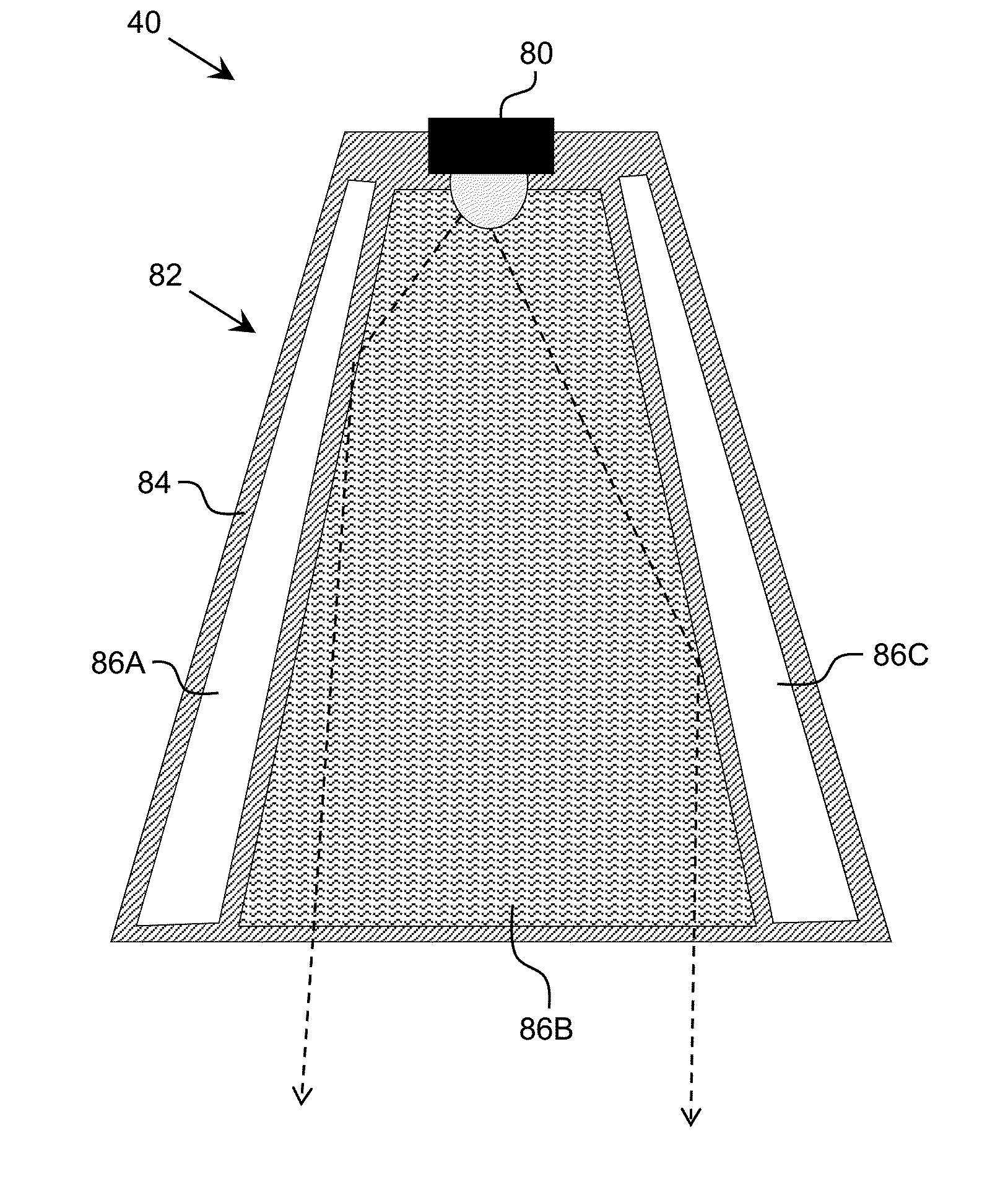
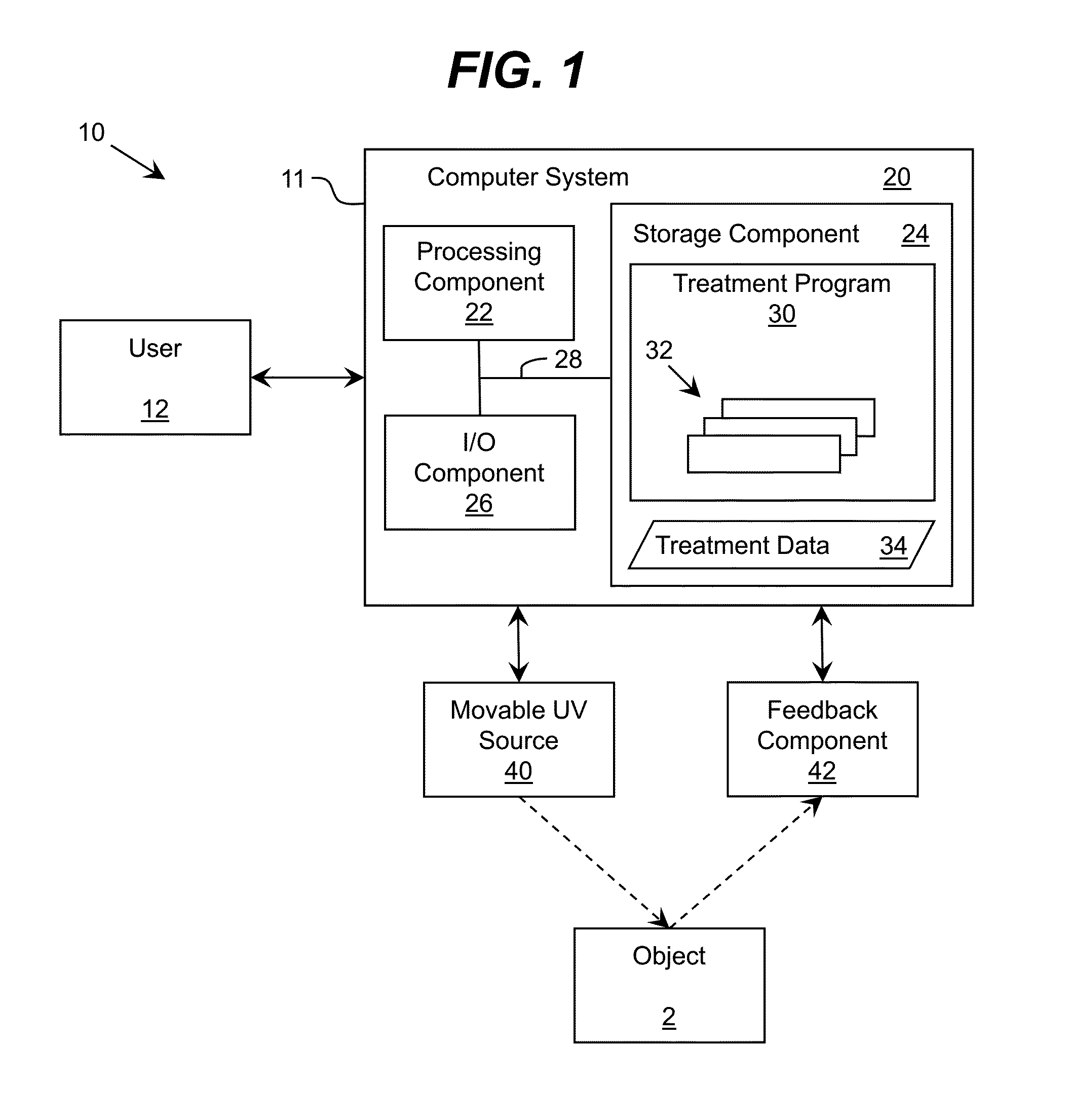
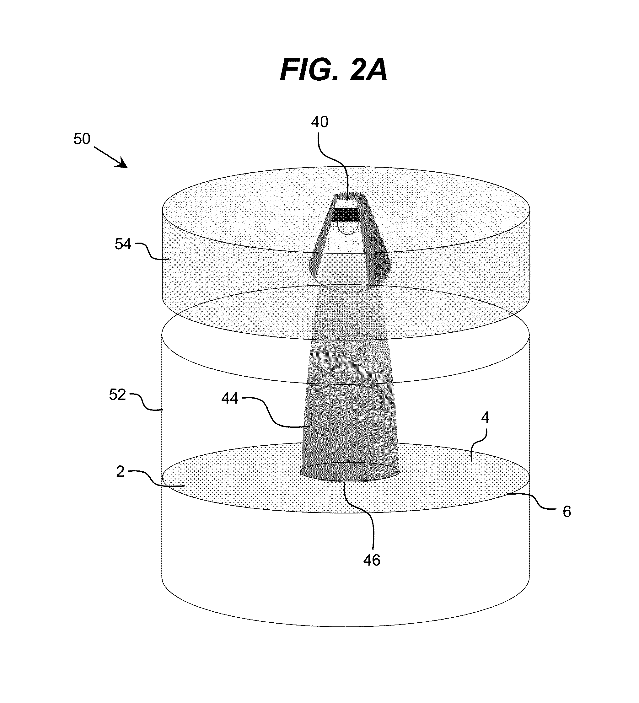
[0026]As indicated above, aspects of the invention provide a solution for treating a surface with ultraviolet radiation. A movable ultraviolet source is utilized to emit a beam of ultraviolet radiation having a characteristic cross-sectional area smaller than an area of the surface to be treated. The movable ultraviolet source can be moved as necessary to directly irradiate any portion of the surface with radiation within the characteristic cross-sectional area of the beam of ultraviolet radiation. The movement can include, for example, rotational movement and / or repositioning the movable ultraviolet source with respect to the surface.

[0027]As used herein, unless otherwise noted, the term “set” means one or more (i.e., at least one) and the phrase “any solution” means any now known or later developed solution. Furthermore, as used herein, ultraviolet radiation / light means electromagnetic radiation having a wavelength ranging from approximately 10 nanometers (nm) to approximately 400...


PUM


Abstract

A solution for treating a surface with ultraviolet radiation is provided. A movable ultraviolet source is utilized to emit a beam of ultraviolet radiation having a characteristic cross-sectional area smaller than an area of the surface to be treated. The movable ultraviolet source can be moved as necessary to directly irradiate any portion of the surface with radiation within the characteristic cross-sectional area of the beam of ultraviolet radiation. The movement can include, for example, rotational movement and / or repositioning the movable ultraviolet source with respect to the surface.

Description

REFERENCE TO RELATED APPLICATIONS[0001]The current application claims the benefit of U.S. Provisional Application No. 62 / 058,062, which was filed on 30 Sep. 2014, which is hereby incorporated by reference.TECHNICAL FIELD[0002]The disclosure relates generally to ultraviolet radiation, and more particularly, to a solution for utilizing a movable ultraviolet radiation source.BACKGROUND ART[0003]Reliable, hygienic storage of sanitary and biological items, such as food, is a major problem. For example, the problem is present throughout the food industry, e.g., manufacturers, retailers, restaurants, and in every household, and is especially significant for food service establishments, in which related issues of food quality control also are significant. In addition to food storage and quality control in fixed locations (e.g., a refrigerator) where access to electricity is readily available, proper food storage and quality control also is important in situations for which access to unlimit...

Claims


Application Information

Patent Timeline
IPC IPC(8): A23L3/28A23L3/00
CPCA23L3/28A23V2002/00A23L3/001B65D81/24
Inventor DOBRINSKY, ALEXANDERSHUR, MICHAELGASKA, REMIGIJUS
Owner SENSOR ELECTRONICS TECH
Learn More