Depth measurement apparatus, imaging apparatus, and depth measurement method
a technology of depth measurement and depth measurement, applied in the field of depth measurement apparatus, can solve the problems of reducing depth accuracy, high calculation load, and increasing calculation load for alignment processing, and achieve the effect of accurate alignment and reducing depth accuracy
- Summary
- Abstract
- Description
- Claims
- Application Information
AI Technical Summary
Benefits of technology
Problems solved by technology
Method used
Image


Examples
first embodiment
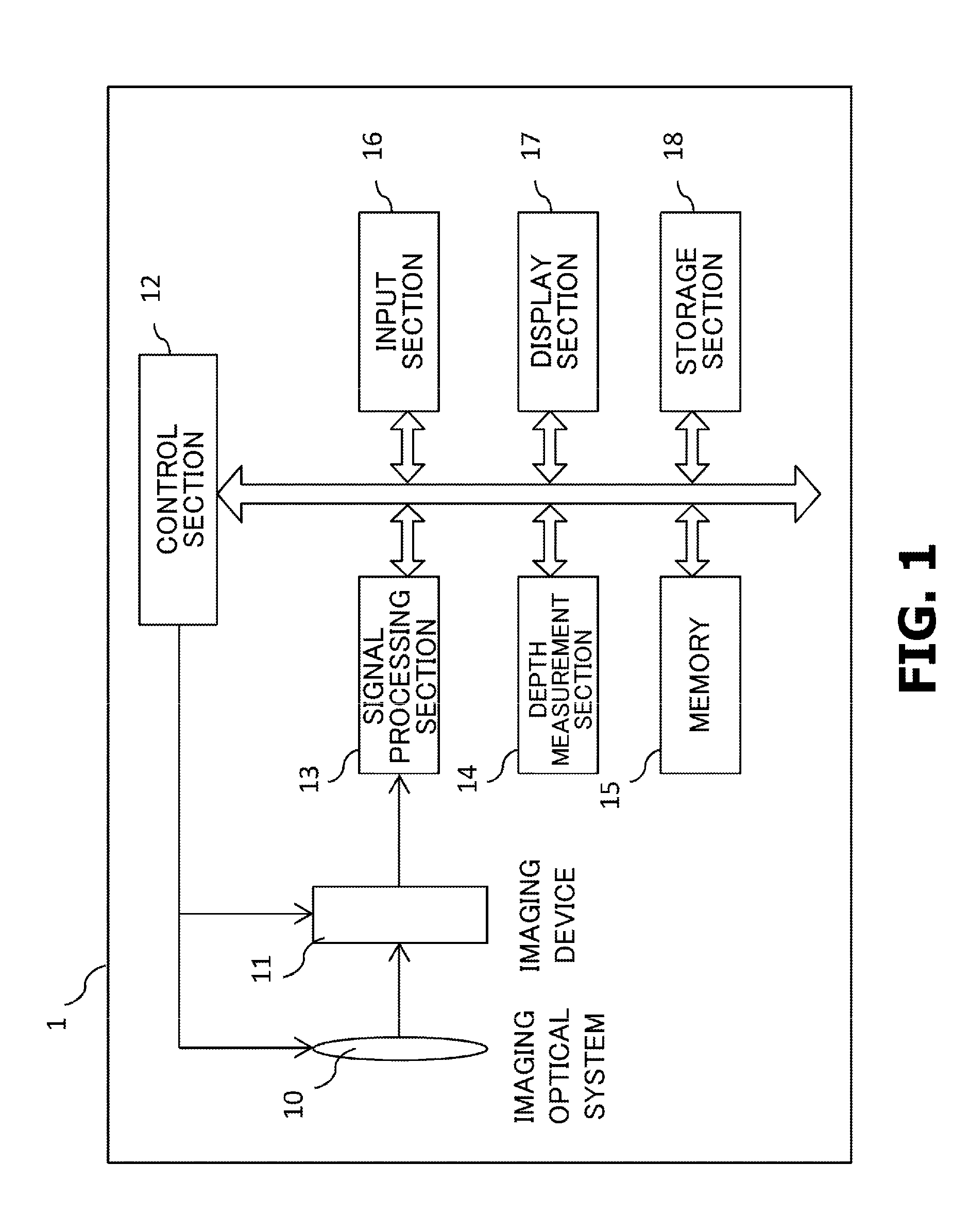
[0023]FIG. 1 is a system configuration diagram of an imaging apparatus according to a first embodiment of the present invention. An imaging apparatus 1 has an imaging optical system 10, an imaging device 11, a control section 12, a signal processing section 13, a depth measurement section 14, a memory 15, an input section 16, a display section 17, and a storage section 18.
[0024]The imaging optical system 10 is an optical system including a plurality of lenses to form incident light into an image on an image plane in the imaging device 11. In the present embodiment, the imaging optical system 10 is an optical system with a variable focus and enables automatic focusing using an autofocus function of the control section 12. An autofocus scheme may be passive or active.
[0025]The imaging device 11 is an imaging device with a CCD or a CMOS and acquires color images. The imaging device 11 may be an imaging device with a color filter or an imaging device with three CCDs for different colors...
second embodiment
[0063]A second embodiment corresponds to the first embodiment to which an alignment process for the color planes is added. The configuration of the imaging apparatus 1 in the second embodiment is similar to the configuration of the imaging apparatus 1 in the first embodiment. The depth measurement process in the second embodiment is also similar to the depth measurement process in the first embodiment except for the depth map generation process S16. The depth map generation process S16, which is a difference from the first embodiment, will be described below. FIG. 5 is a flowchart illustrating a flow of the depth map generation process S16 in the second embodiment.
[0064]Upon receiving an image, the depth measurement section 14 executes, in step S41, a process of eliminating misalignment between two color planes caused by lateral chromatic aberrations (hereinafter referred to as an alignment process). The size of an image differs between the color planes due to the chromatic aberrati...
third embodiment
[0068]A third embodiment is an embodiment in which two color planes are selected for each local area. A configuration of the imaging apparatus 1 in the third embodiment is similar to the configuration of the imaging apparatus 1 in the first embodiment. A flow of the depth measurement process in the third embodiment is substantially similar to the flow of the depth measurement process in the first embodiment (FIG. 2) except that the selection of color planes in step S14 in the first embodiment is performed, in the third embodiment, within the depth map generation process in step S16. That is, compared to the depth measurement process in the first embodiment, the depth measurement in the third embodiment is performed, in which the processing in step S14 is omitted from the flowchart illustrated in FIG. 2 and in which the contents of the depth map generation process in step S16 are different from the contents of the depth map generation process in step S16 in the flowchart illustrated ...
PUM
 Abstract
Description
Claims
Application Information
 - R&D
- Intellectual Property
- Life Sciences
- Materials
- Tech Scout
- Unparalleled Data Quality
- Higher Quality Content
- 60% Fewer Hallucinations
Browse by: Latest US Patents, China's latest patents, Technical Efficacy Thesaurus, Application Domain, Technology Topic, Popular Technical Reports.
© 2025 PatSnap. All rights reserved.Legal|Privacy policy|Modern Slavery Act Transparency Statement|Sitemap|About US| Contact US: help@patsnap.com