
Produced water steam generation process using produced water boiler with gas turbine

a technology of produced water and gas turbine, which is applied in the direction of fluid removal, insulation, borehole/well accessories, etc., can solve the problems of large amount of downtime in cleaning the boiler tube, ineffective heat transfer of the boiler, and large amount of downtime of the boiler tube, so as to avoid duplication of heat transfer surface area and add value. , the effect of simplifying the lin

Inactive Publication Date: 2016-03-17
HUSKY OIL OPERATIONS
View PDF10 Cites 4 Cited by
  • Summary
  • Abstract
  • Description
  • Claims
  • Application Information

AI Technical Summary

Benefits of technology

The present invention provides a system for generating steam from produced water with a simplified and value-added line-up that avoids heat transfer surface area duplication and minimizes the need for boiler feedwater treating.

Problems solved by technology

For example, in the case of heavy oil and bitumen housed in subsurface reservoirs, conventional drive mechanisms may be inadequate to enable production to surface, and it is well known to therefore inject steam or steam-solvent mixtures to make the heavy hydrocarbon more amenable to movement within the reservoir permeability pathways, by heating the hydrocarbon and / or mixing it with lighter hydrocarbons or hot water.
Conventional drum boilers operating at circa 2% blowdown cannot typically be used to generate steam from the produced water without using evaporators to generate high purity feedwater due to the concentration of dissolved salts and impurities such as calcium, silica, organics and the like that cause precipitation and thereby scaling within boiler tubes during the boiling of the water, which thereby very quickly renders the boiler ineffective in transferring heat to the water to generate steam and can also rupture boiler tubes due to the generation of hot spots.
For example, OTSGs still require boiler feedwater pretreatment, require large volumes of feedwater since much of the feed is rejected downhole as blowdown to manage impurities, and can suffer large amounts of downtime to clean boiler tubes (pigging).
However, alternative drum boilers require the use of evaporation technology, which adds significant capital expense and requires high energy consumption.
However, indirect boiling technologies currently under consideration are often complex and likely relatively expensive to implement as they may contain double the heat transfer surface area than what is required to generate steam alone.

Method used


Image

  • Produced water steam generation process using produced water boiler with gas turbine
  • Produced water steam generation process using produced water boiler with gas turbine
  • Produced water steam generation process using produced water boiler with gas turbine

Examples


Embodiment Construction

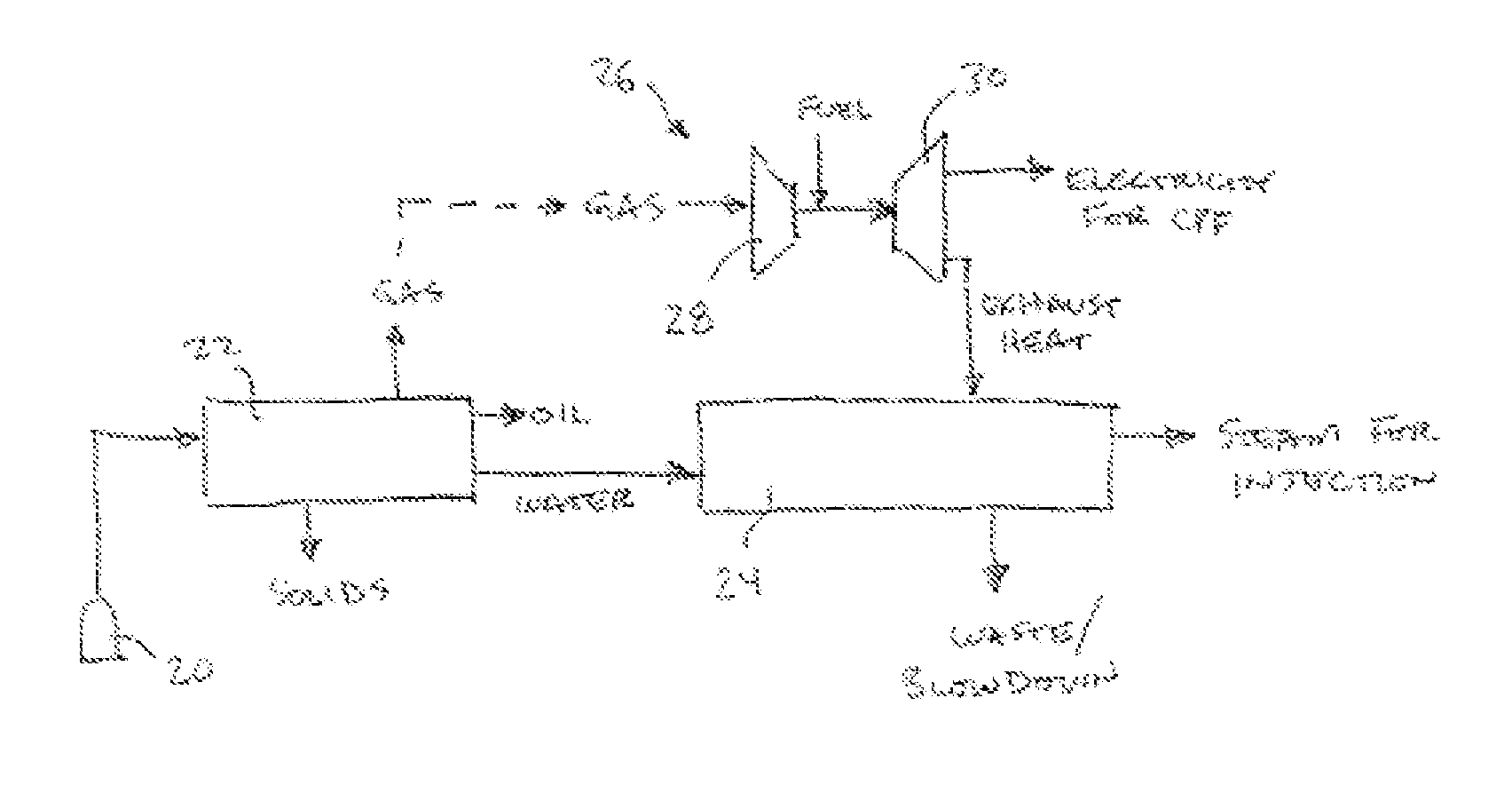
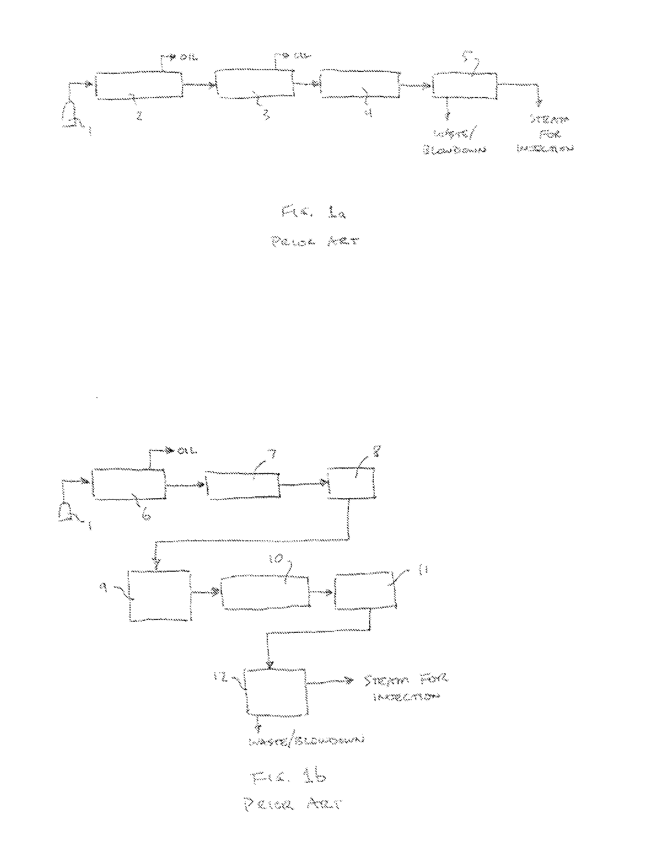
[0022]As mentioned above, conventional produced water steam generation systems involve a number of subsystems to separate and purify the produced water to a state that is acceptable as feedwater for the steam generation equipment. As is shown in FIG. 1A, the subsystems of a conventional prior art system for processing water produced from a wellhead 1 include a gas / oil / free water / solids separation stage 2, a produced water removal stage 3, a produced water treatment impurity removal stage 4 and steam generation 5. The oil / produced water separation stage 2 is designed to remove most of the oil from the water, the oil then being stored or pipelined elsewhere for processing, while the produced water—still somewhat contaminated with minor amounts of oil—must undergo additional processing in the oil removal stage 3 (in which further removed oil is recovered and processed). The produced water treatment impurity removal stage 4, as discussed above, removes various impurities from the de-oil...


PUM


Abstract

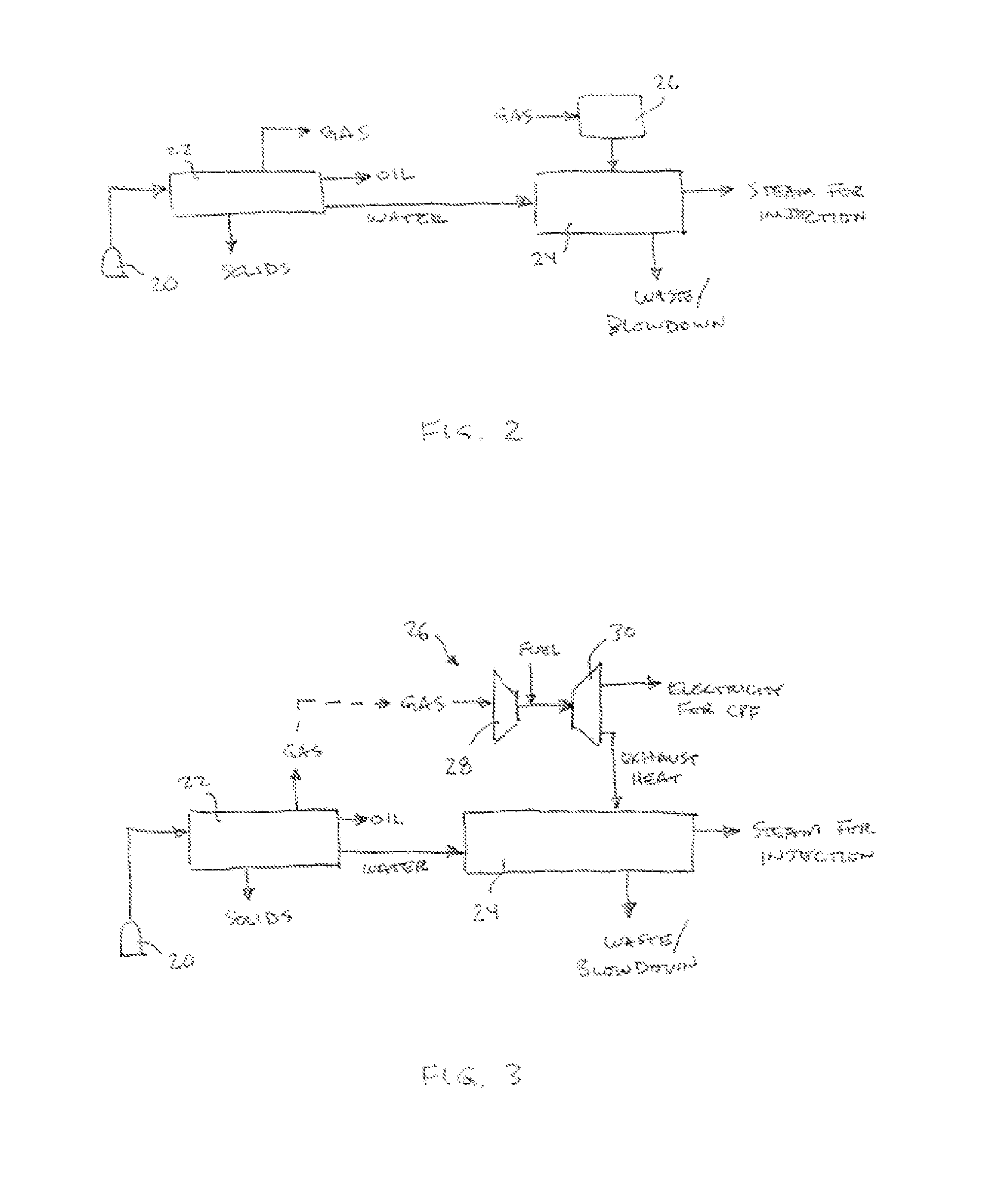
A method and system for producing steam for use in heavy hydrocarbon recovery operations. Water, containing impurities, produced from the well is separated from hydrocarbons and other materials, and subsequently directly passed to a produced water boiler with online pigging. The boiler is indirectly heated by means of a hot flue gas, such as a gas turbine exhaust, which produces electricity (for powering a central processing facility, or alternatively a burner to heat the boiler) and exhaust heat for heating the boiler.

Description

CROSS-REFERENCE TO RELATED APPLICATION[0001]This application claims the benefit of and priority to U.S. Provisional Patent Application Serial No. 62 / 050,894, filed Sep. 16, 2014, entitled “Produced Water Steam Generation Process Using Produced Water Boiler with Gas Turbine,” the contents of which are incorporated herein in its entirety for all purposes.FIELD OF THE INVENTION[0002]The invention relates to thermal recovery methods and systems for heavy hydrocarbon deposits, and specifically to such methods and systems requiring steam injection to mobilize the deposits.BACKGROUND[0003]In the field of subsurface hydrocarbon production, it is known to employ various stimulation procedures and techniques to enhance production. For example, in the case of heavy oil and bitumen housed in subsurface reservoirs, conventional drive mechanisms may be inadequate to enable production to surface, and it is well known to therefore inject steam or steam-solvent mixtures to make the heavy hydrocarbon...

Claims


Application Information

Patent Timeline
IPC IPC(8): E21B43/24
CPCE21B43/24E21B36/025
Inventor BERNAR, RODGER FRANCESCOBURG, BERTRAND FRANCOIS MATHIASJIA, LEI
Owner HUSKY OIL OPERATIONS
Learn More