Woven retention devices, systems, packaging, and related methods

a technology of woven retention devices and woven strips, applied in the field of woven retention device kits and systems, can solve the problems of loss of purchase and holding strength of bone screws, loss of fixation or grip between bone screws and patient's bones, and stripping of holes, etc., and achieve the effect of increasing or decreasing the number o

Inactive Publication Date: 2016-03-17
WOVEN ORTHOPEDIC TECH
View PDF0 Cites 8 Cited by
  • Summary
  • Abstract
  • Description
  • Claims
  • Application Information

AI Technical Summary

Benefits of technology

The patent describes an apparatus for measuring and cutting a woven retention device used in bones. The apparatus includes a hollow tube that can hold the device, a cutting implement, and an advancement mechanism that can move the device within the tube to different positions. The apparatus allows for easy and accurate cutting of the woven retention device to a desired length.

Problems solved by technology

One complication with the use of bone screws is the loss of fixation or grip between the bone screw and the patient's bone.
Another complication with the use of bone screws is the stripping of the hole in the bone when the bone screw is inserted.
This results in the loss of purchase and holding strength of the bone screw.
The presence of osteoporotic bone can increase the likelihood of complications by reducing the purchase or grip of the bone screw to the patient's bone, resulting in a loss of holding strength and loosening of the bone screw or pullout of the bone screw.
Current solutions to secure bone screws have not adequately addressed screw failure and the underlying causes of screw failure.

Method used


Image

  • Woven retention devices, systems, packaging, and related methods
  • Woven retention devices, systems, packaging, and related methods
  • Woven retention devices, systems, packaging, and related methods

Examples


examples

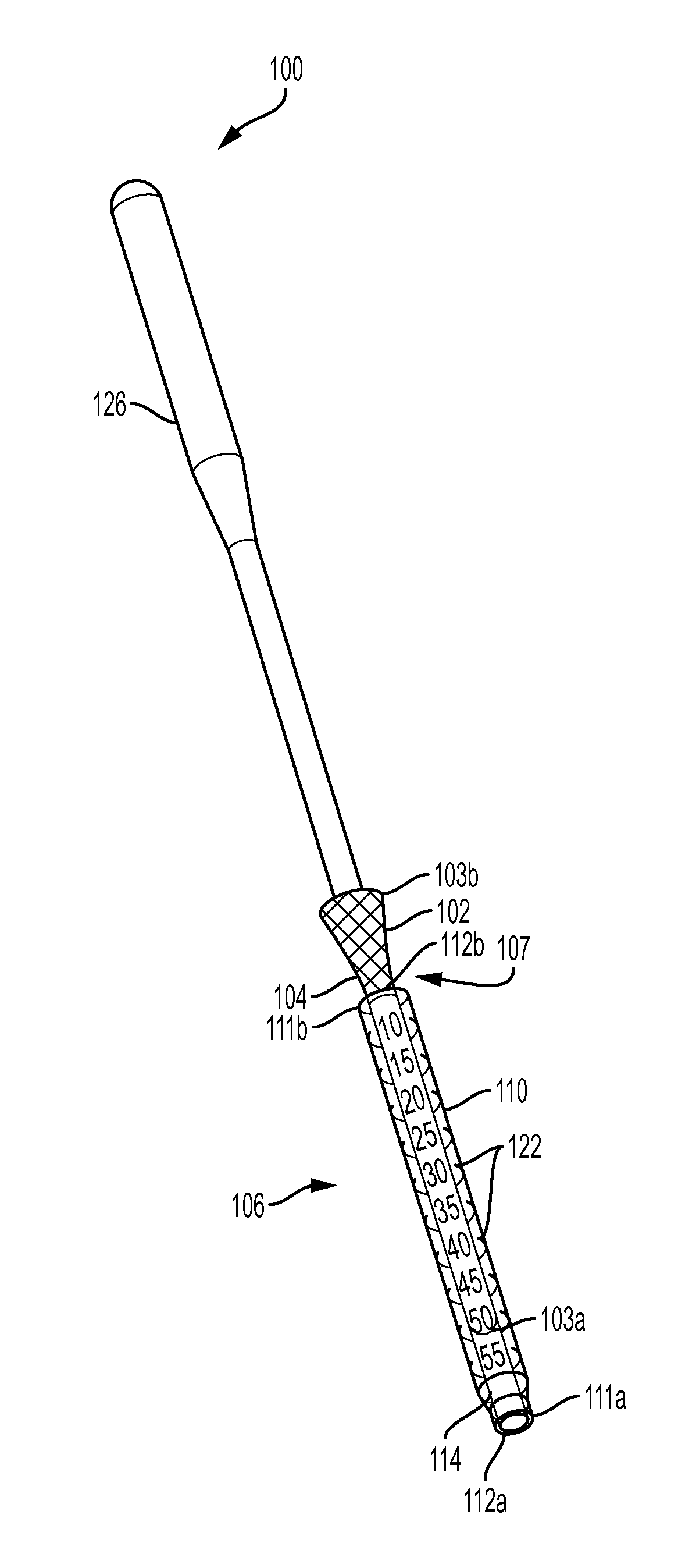
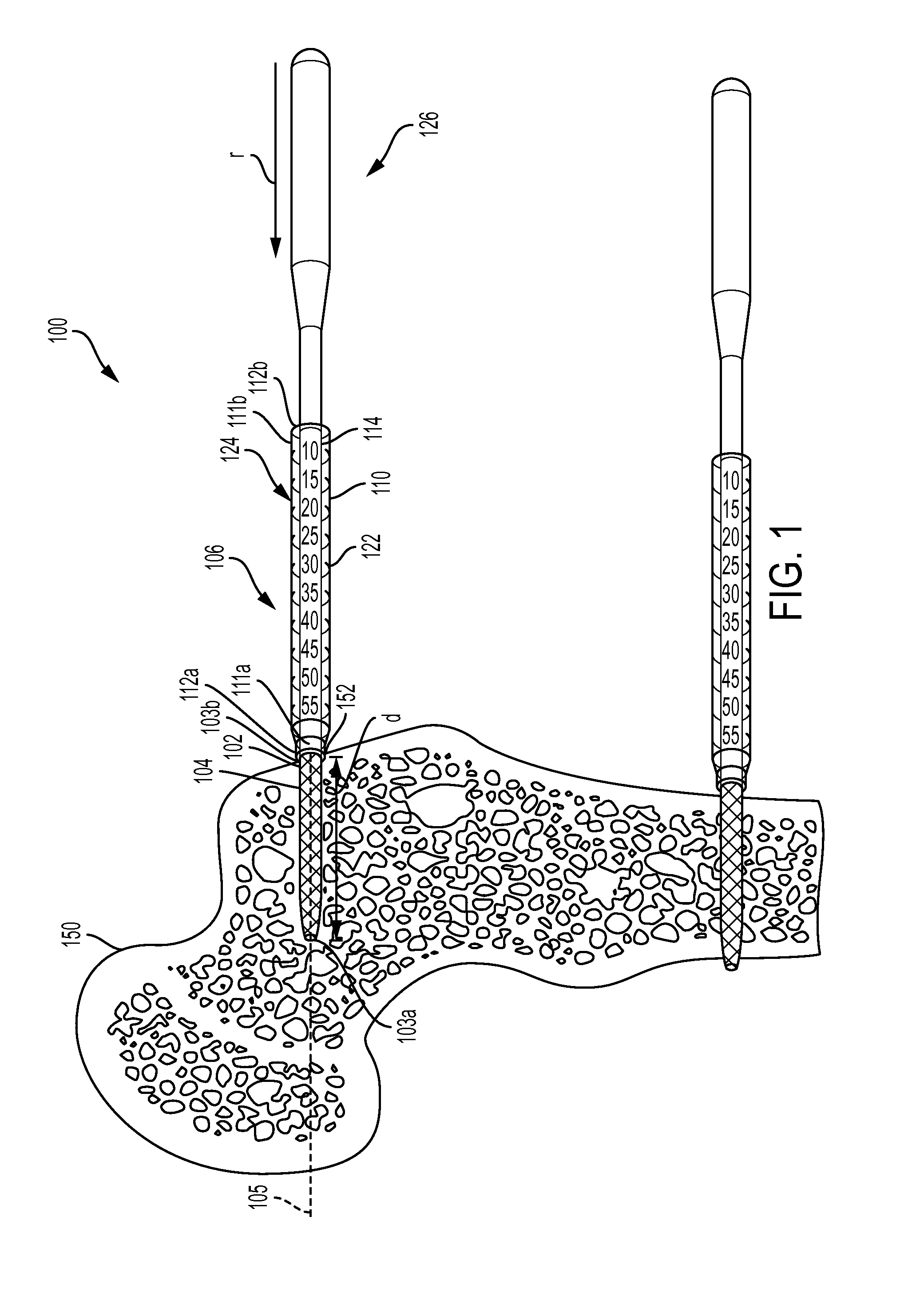
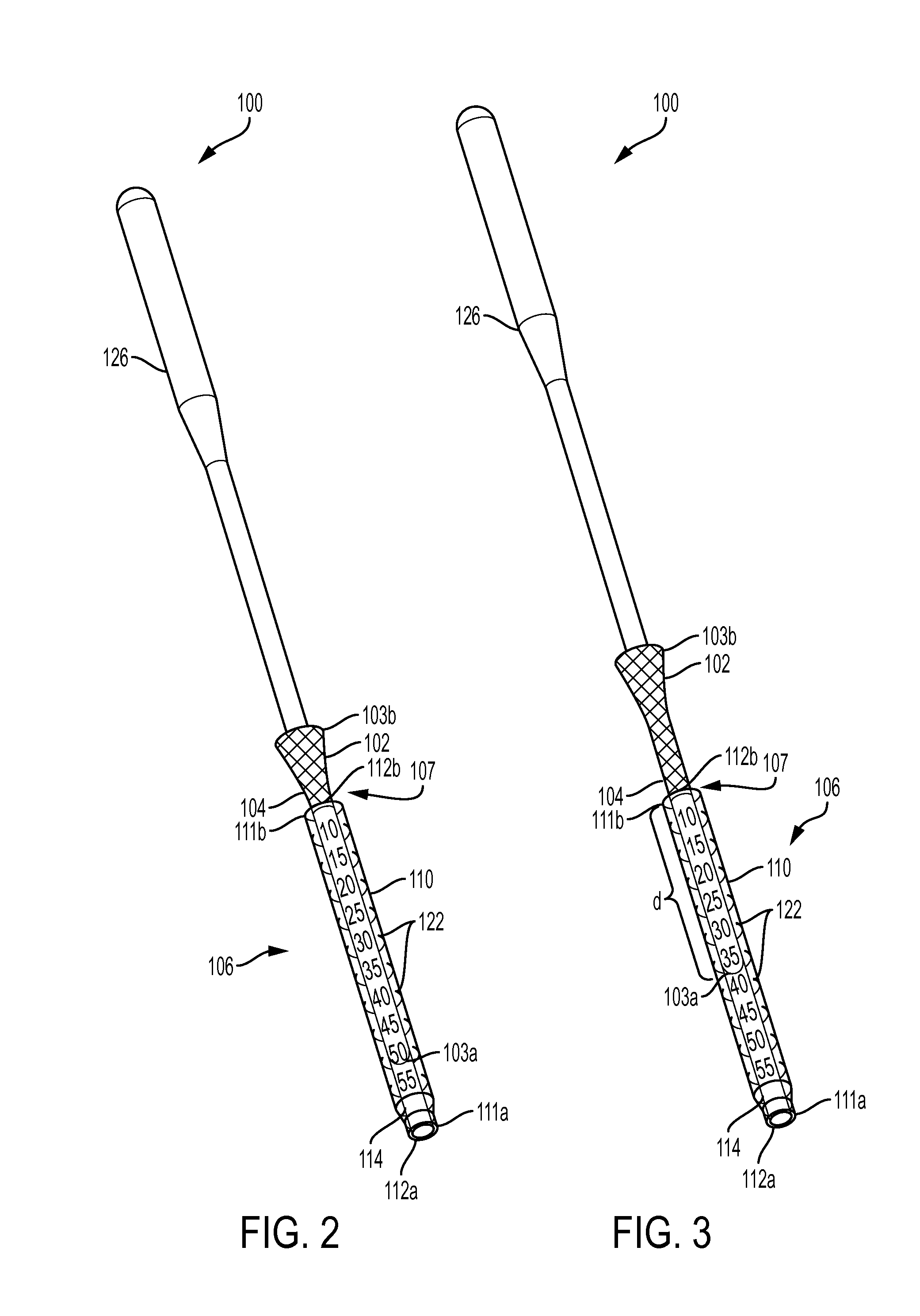
[0121]The following is provided as an example of sizes and dimensions of a delivery tube and push rod according to an example of one embodiment of the invention. However, embodiments are not limited to the following dimensions.

[0122]The push rod may be formed of stainless steel (e.g., 316 SS). In an embodiment where the push rod is formed without the bent portion, the push rod may have an overall length of 300 mm, where a handle portion of the push rod may be about 50 mm long and the elongated arm that is inserted into the delivery tube and woven retention device may be 250 mm. In an embodiment where the push rod is formed with the bent portion, the overall length may be shorter. The elongated are may have a diameter of about 2 mm. The diameter of the elongated arm may be smaller or larger, as long as the elongated arm is able to slide within the delivery tube and push the woven retention device. The handle portion may have a diameter of 8 mm, for example.

[0123]The delivery tube may...


PUM


Abstract

A system for preparing and inserting a woven retention device into bone is provided. The system includes a woven retention device having a distal end, a proximal end for receiving a fastener, and a sleeve body between the distal and proximal ends. A longitudinal axis extends between the distal and proximal ends. The system also includes a measuring device surrounding at least a portion of the woven retention device and defining a cutting position at which the woven retention device is to be cut for insertion into a hole in the bone. The measuring device measures a distance from the distal end of the woven retention device to the cutting position. The woven retention device is movable relative to a least a portion of the measuring device that defines the cutting position such that the woven retention device can be cut to a desired size.

Description

CROSS-REFERENCE TO RELATED APPLICATIONS[0001]This application claims priority to U.S. Provisional Application No. 62 / 051,095, filed Sep. 16, 2014, the disclosure of which is incorporated herein by reference in its entirety.TECHNICAL FIELD OF INVENTION[0002]The present invention relates generally to woven retention device kits, systems, and methods for inserting a woven retention device into bone.BACKGROUND[0003]In orthopedic surgery it is common to secure a bone screw to a patient's bone. Bone fracture repair is surgery to fix a broken bone using plates, nails, screws, or pins. It is common in the treatment of fractures to attach a plate to the bone utilizing bone screws. The resulting construct prevents motion of the fractured bone so that the bone can heal. Alternatively, one or more screws may be inserted across the break to hold it place.[0004]In the treatment of spinal disorders, pedicle screws are inserted into the patient's vertebrae to serve as anchor points that can then be...

Claims


Application Information

Patent Timeline
Patent Type & Authority Applications(United States)
IPC IPC(8): A61B17/86
CPCA61B17/869A61B2017/8655A61B2019/461A61B2017/0409A61B17/686A61B17/8863A61B2090/061
Inventor MCDONNELL, CHRISTOPHERRICHARDS, ROBERT L.SROKA, NICOLE S.CORRAO, JR., ERNEST N.LITKE, JR., RONALD G.
Owner WOVEN ORTHOPEDIC TECH
Why Eureka
Try Eureka