
Machine tool having Anti-vibration tuning mechanism for chatter minimized machining

a technology of vibration dampening and tuning mechanism, which is applied in the direction of shock absorbers, manufacturing tools, instruments, etc., can solve the problems of noisy machining operations and rough machined surfaces, and achieve the effect of eliminating vibration and chattering of machine tools during machining and efficient tuning of vibration dampening characteristics

Inactive Publication Date: 2016-03-10
GIANNETTI ENRICO R
View PDF20 Cites 34 Cited by
  • Summary
  • Abstract
  • Description
  • Claims
  • Application Information

AI Technical Summary

Benefits of technology

The present invention provides a machine tool for supporting a replaceable cutter and minimizing tool chatter during machining. It has an internal vibration absorbing mass and a tuning mechanism that can be adjusted by a machinist to absorb or cancel the resonant frequency of the tool. The machine tool holder also has an anti-vibration tuning mechanism for adjusting the vibration dampening characteristics of the vibration absorbing mass. These features allow for smooth and efficient cutting of precision metal surfaces on a rotating work-piece.

Problems solved by technology

Machining vibration, typically referred to as “chatter”, especially when relatively long and somewhat flexible machine tools such as boring bars are used, interferes with optimum machining activity and usually results in roughly machined surfaces and noisy machining operations when machining internal and external surfaces, threads and the like within or on metal stock that is rotated by a machining system.

Method used


Image

  • Machine tool having Anti-vibration tuning mechanism for chatter minimized machining
  • Machine tool having Anti-vibration tuning mechanism for chatter minimized machining
  • Machine tool having Anti-vibration tuning mechanism for chatter minimized machining

Examples


Embodiment Construction

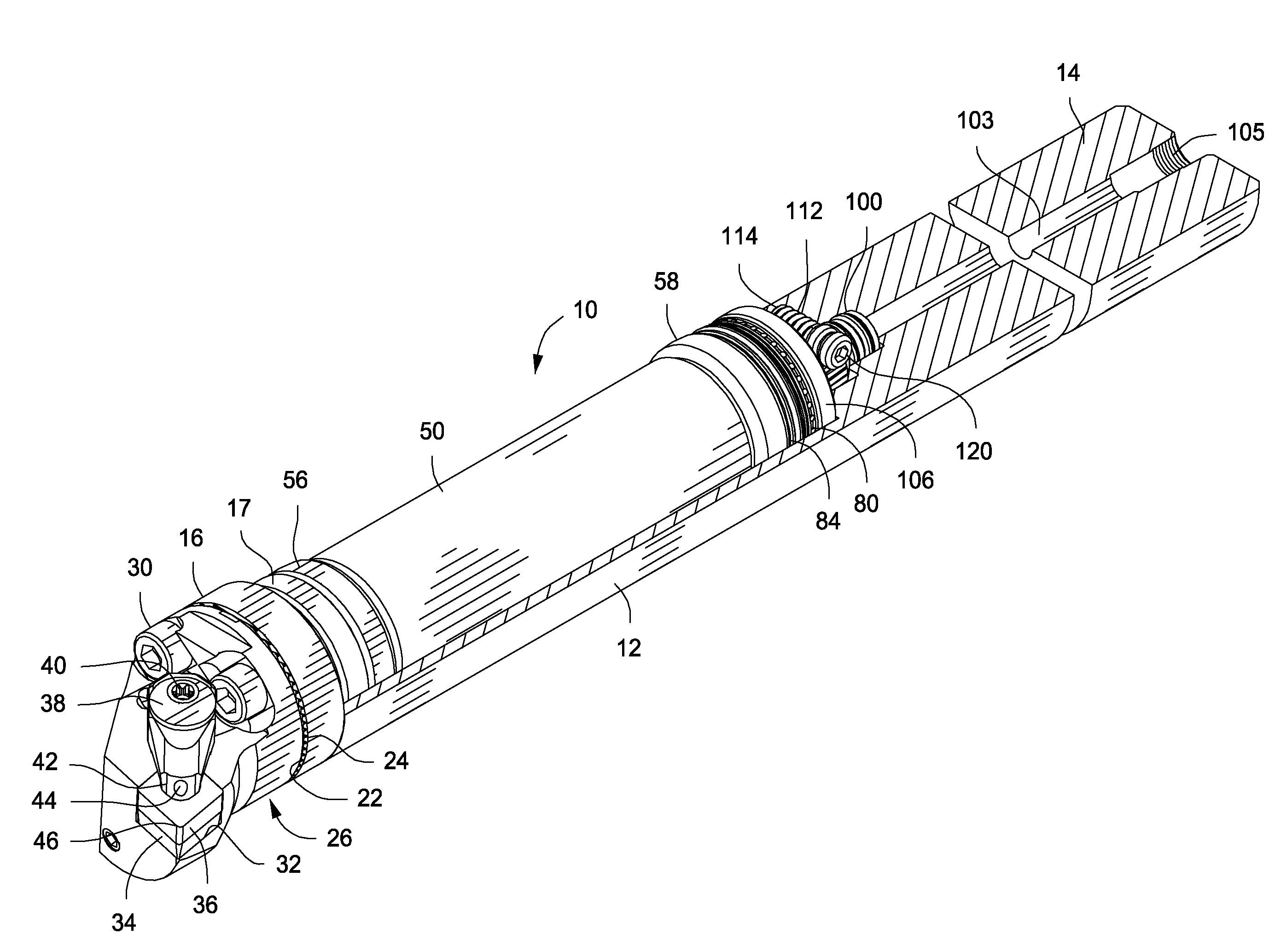
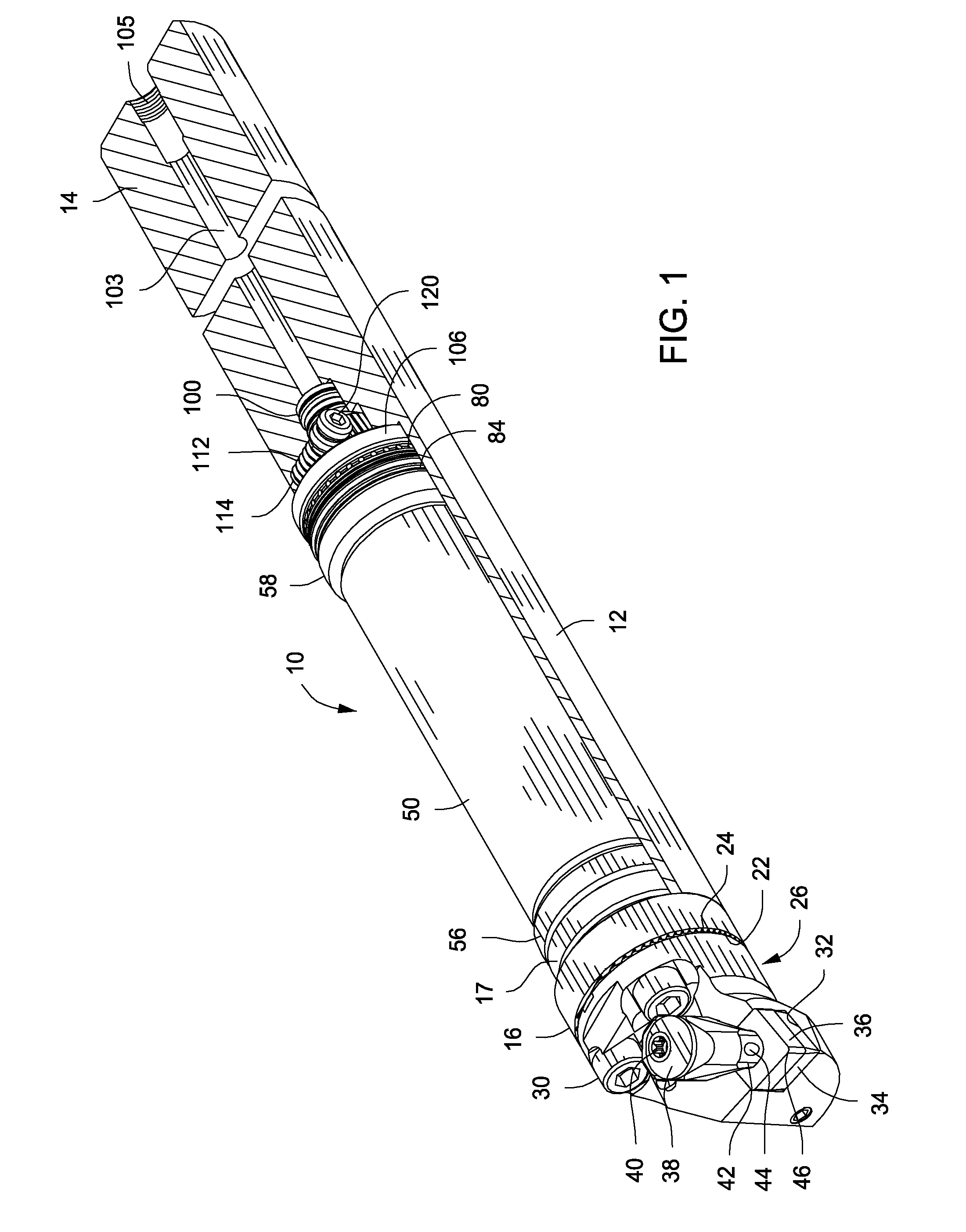
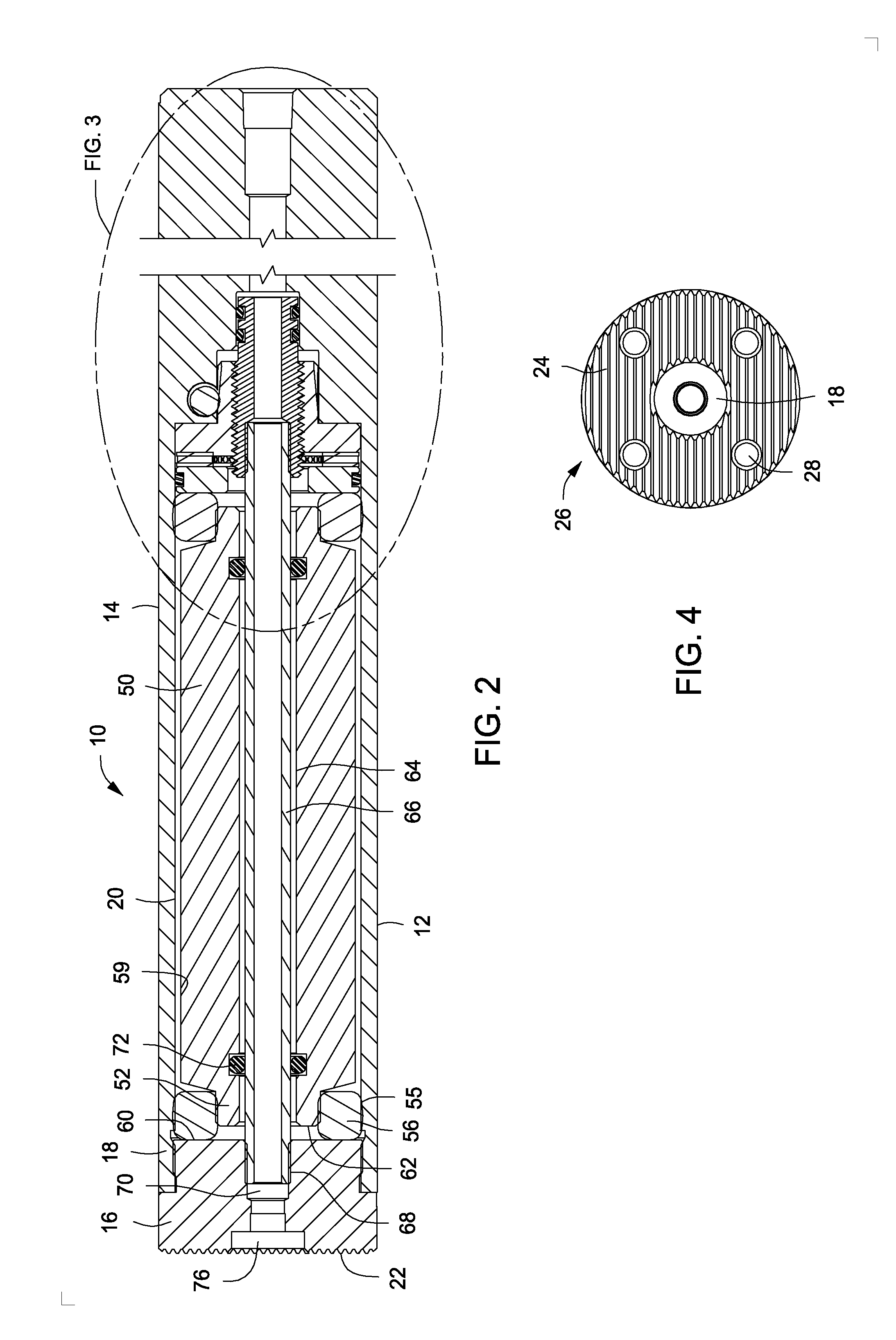
[0040]Referring now to the drawings and first to the partial longitudinal section view of FIG. 1, an anti-vibration adjustable machine tool holder embodying the principles of the present invention is shown generally at 10 and is in the form of a boring bar that is intended to be used to cut cylindrical internal surfaces within a work-piece being machined. The machine tool holder incorporates an adjustable or tunable anti-vibration or anti-chatter machining adjustment mechanism that can be manually adjusted to substantially eliminate the tool holder vibration that is responsible for rough machining of cylindrical surfaces.

[0041]Though the through-coolant capability of the tool holder is not necessary for anti-vibration tuning or adjustment, the machine tool holder preferably provides a coolant handling system to facilitate efficiency of handling and machining. The machine tool holder has an elongate tool body or tool shank 12 having a rear end portion 14 that is adapted to be retaine...


PUM

PropertyMeasurementUnit
forceaaaaaaaaaa
resonant frequencyaaaaaaaaaa
frequencyaaaaaaaaaa

Abstract

A vibration dampening through coolant tool holder, such as a boring bar, for machining operations, has an internal chamber within which a vibration dampening mass is supported at each axial end by resilient buffer members. A vibration adjusting piston is linearly moveable with the tool holder and has dampening adjustment engagement with the mass. A dampening adjustment mechanism causes linear movement of the piston and applies controlled force of the piston to the mass and has a micrometer type rotary adjustment member that imparts linear force to the piston. The linear piston adjustment can also have a worm gear drive mechanism for controlling linear piston movement.

Description

BACKGROUND OF THE INVENTION[0001]1. Field of the Invention[0002]The present invention relates generally to machine tools or tool holders for metal cutting and working machines. More particularly the present invention concerns tool holders including boring bars, threading tools and the like, which because of their length and flexibility are often subject to significant vibration during rotary machining operations. This invention also concerns machine tools that have a through-coolant capability for conducting a flow of pressurized coolant fluid through internal passages of a machine tool and emitting the coolant as a jet or spray that is directed to the cutting interface of a cutting insert with rotating metal stock for cooling and for removal of metal chips that have been cut from the rotating stock.[0003]2. Description of the Prior Art[0004]Machining vibration, typically referred to as “chatter”, especially when relatively long and somewhat flexible machine tools such as boring bar...

Claims


Application Information

Patent Timeline
Patent Type & Authority Applications(United States)
IPC IPC(8): B23B29/12G01M1/02
CPCB23B29/12G01M1/02B23B2260/004B23B2250/04B23B2250/12B23B2250/16B23B27/002B23B27/007F16F7/104
Inventor GIANNETTI, ENRICO, R.
Owner GIANNETTI ENRICO R
Learn More