Eureka AIR delivers breakthrough ideas for toughest innovation challenges, trusted by R&D personnel around the world.

One-piece self-locking nut

a self-locking, threaded technology, applied in the direction of threaded fasteners, screws, fastening means, etc., can solve the problems of occupying more time and material, and the locknut may still be subject to loosening, so as to improve the strength of the nut, the effect of easy and less expensive manufacturing, and convenient manufacturing

Active Publication Date: 2016-02-11
ARNOLD PERMANENT NUT
View PDF1 Cites 7 Cited by
  • Summary
  • Abstract
  • Description
  • Claims
  • Application Information

AI Technical Summary

Benefits of technology

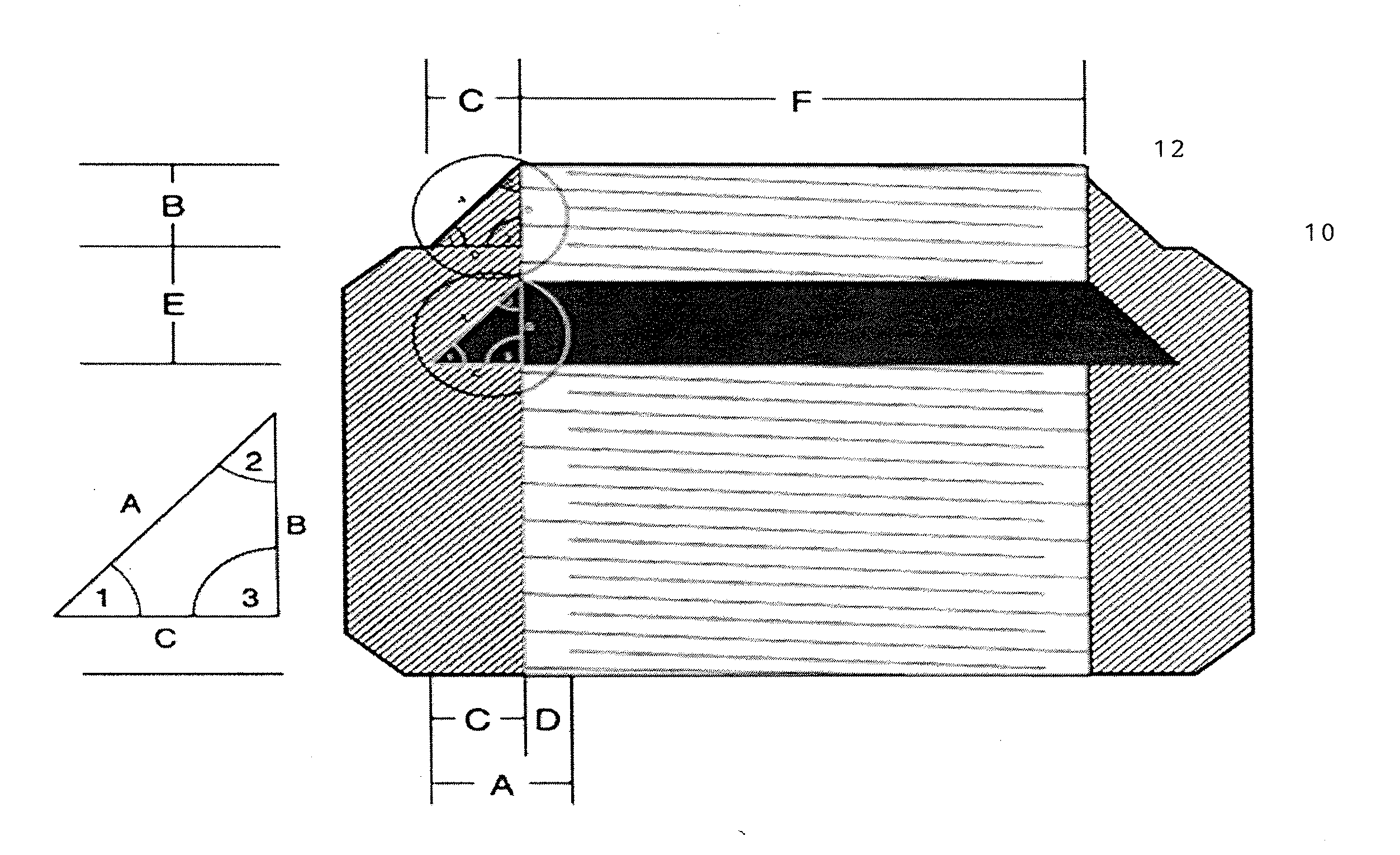
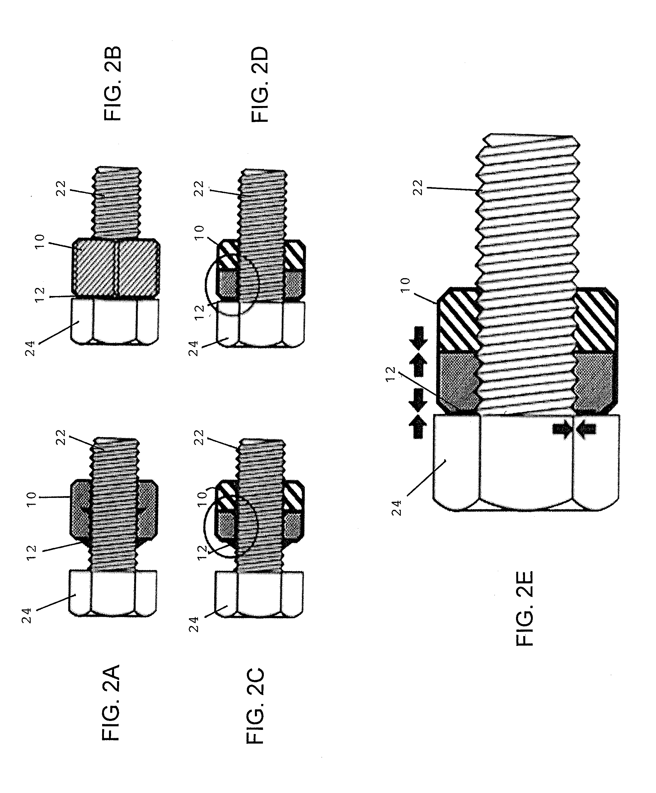
The present invention provides a one-piece self-locking nut for permanent fastening on a bolt that can be easily manufactured and installed with standard tools. The self-locking nut is lighter, stronger, and quicker to install than two-piece counterparts, and its unique design ensures a secure lock that is not prone to loosening. Additionally, the self-locking nut is easier to manufacture, with standard nut manufacturing methods being used to create it. The front part of the nut acts as a "jam nut," while the rear part has a front indentation space that acts as an inner relief cut. These two parts are joined together by circumferential welding and flattening of the front part into the rear part, leaving a small gap between them. This design ensures a secure lock that is not prone to loosening.

Problems solved by technology

However, the conventional use of locknuts requires added components to be used and manipulated with every permanent fastener, thereby taking up more time and material, and such locknuts may still be subject to loosening over time in high vibration environments.

Method used


Image

  • One-piece self-locking nut
  • One-piece self-locking nut
  • One-piece self-locking nut

Examples


Embodiment Construction

[0019]In the following detailed description of the invention, certain preferred embodiments are illustrated providing certain specific details of their implementation. However, it will be recognized by one skilled in the art that many other variations and modifications may be made given the disclosed principles of the invention.

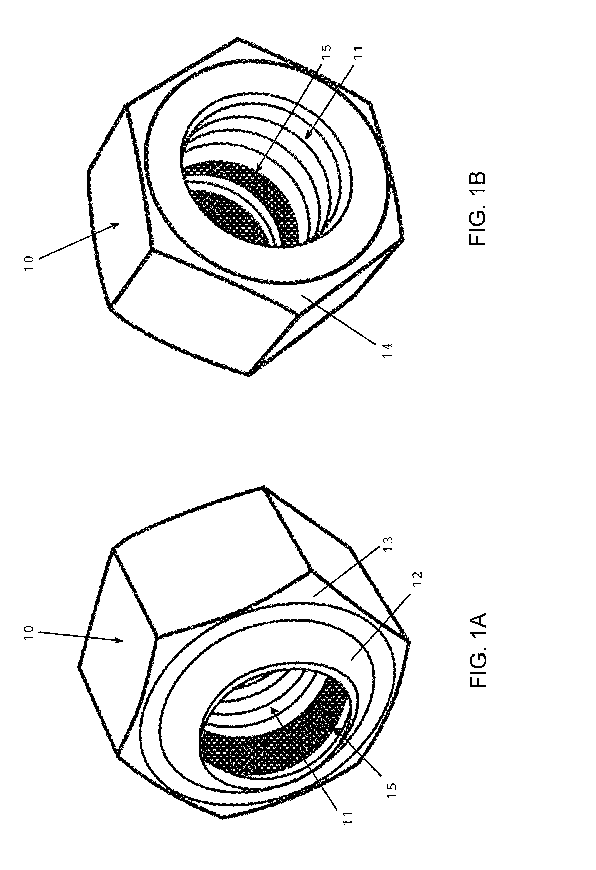
[0020]FIG. 1A is a front perspective view of a preferred embodiment of the one-piece, self-locking nut in accordance with the represent invention, and FIG. 1B is a rear perspective view thereof. The one-piece, self-locking nut has a nut body 10 with internal threading 11 for threading on a threaded shaft of a fastener bolt, and is integrally formed with external, crush-locking lips 12 provided on a forward contact face 13 of the nut body 10. The forward contact face 13 of the nut is typically beveled or provided with a slight convex curvature, while the rear face 14 of the nut is typically planar. The dark area 15 indicates a space for deformation of the crus...


PUM


Abstract

A self-locking nut is formed with a rear nut body with internal threading and a front nut body having circumferentially arranged, crush-locking lips provided on a forward contact face of the front nut body and being spaced from the internal threading of the rear nut body by an internal relief cut for accommodating deformation of the crush-locking lips therein. When the nut is tightened down on an object on a fastener bolt, the crush-locking lips are forced inwardly and deformed on the threaded shaft of the fastener bolt into the space of the internal relief cut in order to form a permanent lock on the fastener bolt. In another preferred embodiment, the self-locking nut has a front “flying saucer” shaped part configured to work like a “jam nut” portion, and a rear “nut body” part having a front indentation space configured to work like an inner relief cut. The two parts are joined together by circumferential welding and flattening of the “flying saucer” part into the inner relief cut space of the “nut body” part while leaving a small gap between the parts.

Description

[0001]This U.S. Patent Application is a continuation-in-part of U.S. patent application Ser. No. 13 / 916,532 filed on Jun. 12, 2013, which claimed the priority filing date of U.S. Provisional Application 61 / 804,693 filed on Mar. 24, 2013, by the same inventor.TECHNICAL FIELD[0002]The present U.S. patent application relates to a threaded nut for fastening on a threaded bolt of any size, pitch, type or material depending on usage specifications and demands.BACKGROUND OF INVENTION[0003]In many applications, it is desirable to have a threaded nut fastened on a threaded bolt with a permanent hold that will not loosen when exposed to high vibration environments. Conventionally, one or more locknuts may be fastened on the bolt behind the threaded nut to apply a locking force on the threaded nut to prevent it from loosening. However, the conventional use of locknuts requires added components to be used and manipulated with every permanent fastener, thereby taking up more time and material, a...

Claims


Application Information

Patent Timeline
IPC IPC(8): F16B39/284F16B39/34
CPCF16B39/34F16B39/284F16B39/026
Inventor LIMATOC, ARNOLD
Owner ARNOLD PERMANENT NUT
Why Eureka
Eureka Blog
Learn More