Steering device
- Summary
- Abstract
- Description
- Claims
- Application Information
AI Technical Summary
Benefits of technology
Problems solved by technology
Method used
Image
Examples
fourth embodiments
First to Fourth Embodiments
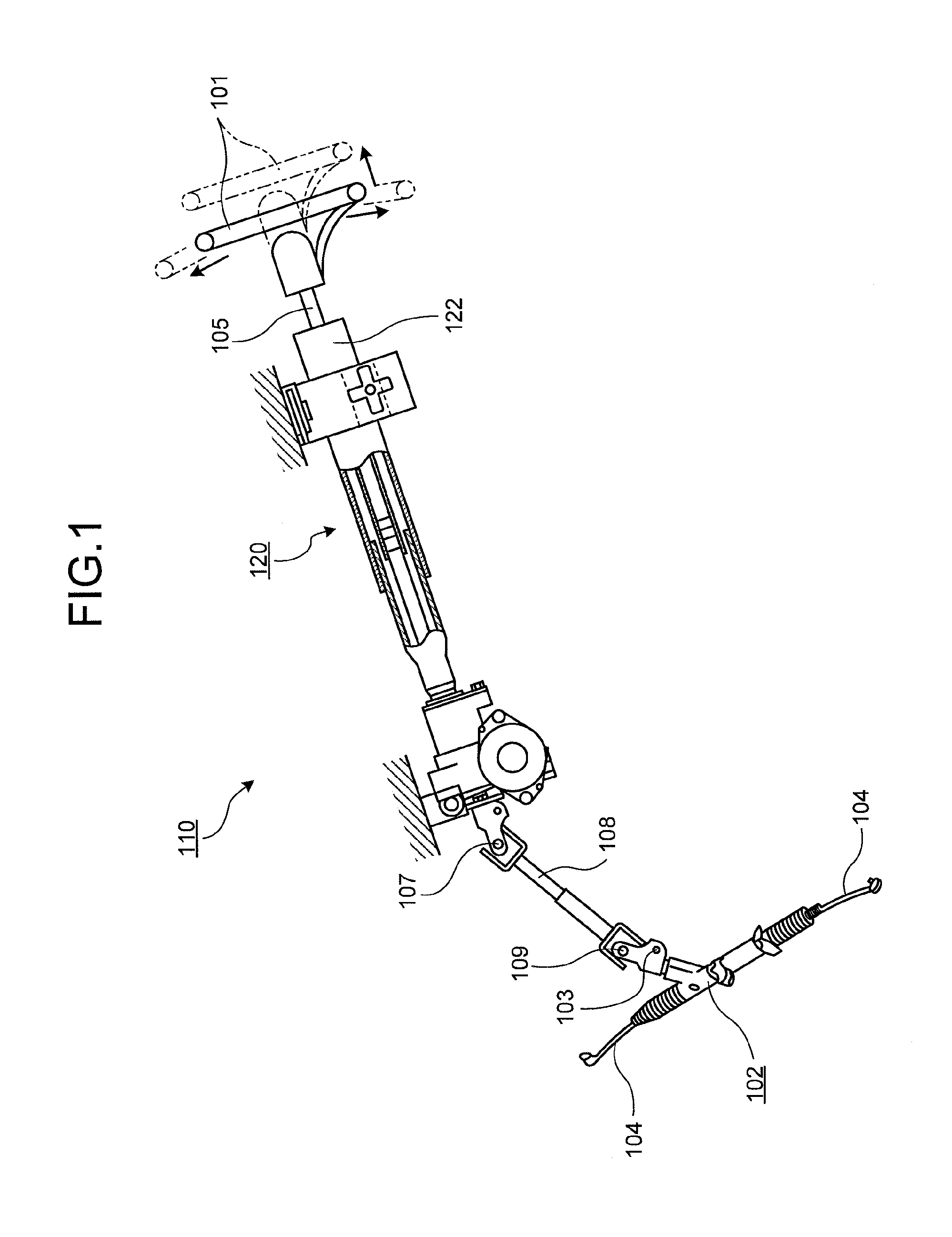
[0064]Hereinafter, this structure will be described in detail with reference to FIGS. 1 to 23D. FIGS. 1 to 4 schematically illustrate the first to fourth embodiments. FIGS. 5 to 10 specifically illustrate the structure of the first embodiment. Similarly, FIGS. 11 to 15 specifically illustrate the structure of the second embodiment, and FIGS. 16 to 23D specifically illustrate the structure of the third embodiment. In FIG. 2, the axial direction DA indicates the axial direction of the steering shaft, and the front side DF and the rear side DB indicate the front side and the rear side of the vehicle body when the steering device is attached to the vehicle body.
[0065]The first embodiment relates to a steering column apparatus 120 that supports a steering shaft including a male steering shaft 106 and a female steering shaft 105. Here, a steering column includes an inner column 121 and an outer column 122 and is contracted in the axial direction so as to be adju...
fifth embodiment
(Modified Example of Fifth Embodiment)
[0116]FIG. 34 is a cross-sectional view illustrating a steering device according to a modified example of the fifth embodiment when taken along the line corresponding to the line e-e of FIG. 26. FIG. 35 is an enlarged diagram illustrating the periphery of the connection member of FIG. 34. FIG. 36 is a diagram illustrating a state after the connection member according to the modified example of the fifth embodiment is sheared. The steering device 100 according to the modified example of the fifth embodiment is different from that of the fifth embodiment in that a connection member P is a resinous pin. In addition, the same reference signs will be given to the same components as those of the above-described embodiments, and the repetitive description thereof will not be presented.
[0117]As illustrated in FIGS. 34 and 35, when the connection member P is inserted into a position straddling the first hole 6h and the second hole 43h, the leg portion 43...
sixth embodiment
(Sixth Embodiment)
[0130]FIG. 37 is a cross-sectional view illustrating a steering device according to a sixth embodiment when taken along the line corresponding to the line e-e of FIG. 26. FIG. 38 is an enlarged diagram illustrating a bottom surface of the steering device according to the sixth embodiment. FIGS. 39A and 39B are perspective views illustrating an inner column bracket according to the sixth embodiment when viewed from the upside and the downside. FIG. 40 is a perspective view illustrating a base plate according to the sixth embodiment. The steering device 100 is different from that of the fifth embodiment in that the connection member P is a ball plunger B. In addition, the same reference signs will be given to the same components as those of the above-described embodiments, and the repetitive description thereof will not be presented.
[0131]As illustrated in FIG. 37, since the ball plunger B is inserted into a position straddling the first hole 6h and the main body scr...
PUM
 Abstract
Description
Claims
Application Information
 - R&D
- Intellectual Property
- Life Sciences
- Materials
- Tech Scout
- Unparalleled Data Quality
- Higher Quality Content
- 60% Fewer Hallucinations
Browse by: Latest US Patents, China's latest patents, Technical Efficacy Thesaurus, Application Domain, Technology Topic, Popular Technical Reports.
© 2025 PatSnap. All rights reserved.Legal|Privacy policy|Modern Slavery Act Transparency Statement|Sitemap|About US| Contact US: help@patsnap.com


