
Drug Delivery Device with Compact Power Unit

a power unit and drug delivery technology, applied in the direction of automatic syringes, wound springs, infusion syringes, etc., can solve the problems of burden, less user-friendly, and reduced finger strength and/or dexterity for people with reduced finger strength and/or dexterity, and achieve the effect of reducing or eliminating at least one drawback

Inactive Publication Date: 2016-02-11
NOVO NORDISK AS
View PDF1 Cites 12 Cited by
  • Summary
  • Abstract
  • Description
  • Claims
  • Application Information

AI Technical Summary

Benefits of technology

The invention describes a power unit that can be used in a compact injection device. The power unit has a high capacity to deliver a number of revolutions to the device's interface, while also providing a constant torque to the interface over its entire range of operation. The power unit is slender and can be used in a pen-type injection device. The axially extending structure, which connects the different coil parts, is flexible and allows for individual contributions to the overall movement of the device. The power unit can be made using a single piece of material and is simple and inexpensive. The activation button for the device is fixed to the axial passage and allows for both coupling and decoupling of the device's interface parts. The technical effects of this invention are a compact, flexible, and powerful power unit that can be used in a syringe-based injection device.

Problems solved by technology

Other injection devices are prefilled when delivered to the user and can only be used until the drug reservoir has been emptied, after which the device is discarded.
The force which must be applied to the push button to perform such an operation is typically not insignificant and may cause handling problems for people with reduced finger strength and / or dexterity.
Some such devices only require the user to apply a small, short-duration force to trigger the injection.
A spring arrangement of the former type requires the user to provide the energy for straining the spring, a requirement which is viewed as burdensome by some people.
This would compromise the slender configuration of the device and result in a less user-friendly, bulky design.

Method used


Image

  • Drug Delivery Device with Compact Power Unit
  • Drug Delivery Device with Compact Power Unit
  • Drug Delivery Device with Compact Power Unit

Examples


Embodiment Construction

[0060]When in the following relative expressions, such as “clockwise” and “counter-clockwise”, are used, these refer to the appended figures and not necessarily to an actual situation of use. The shown figures are schematic representations for which reason the configuration of the different structures as well as their relative dimensions are intended to serve illustrative purposes only.

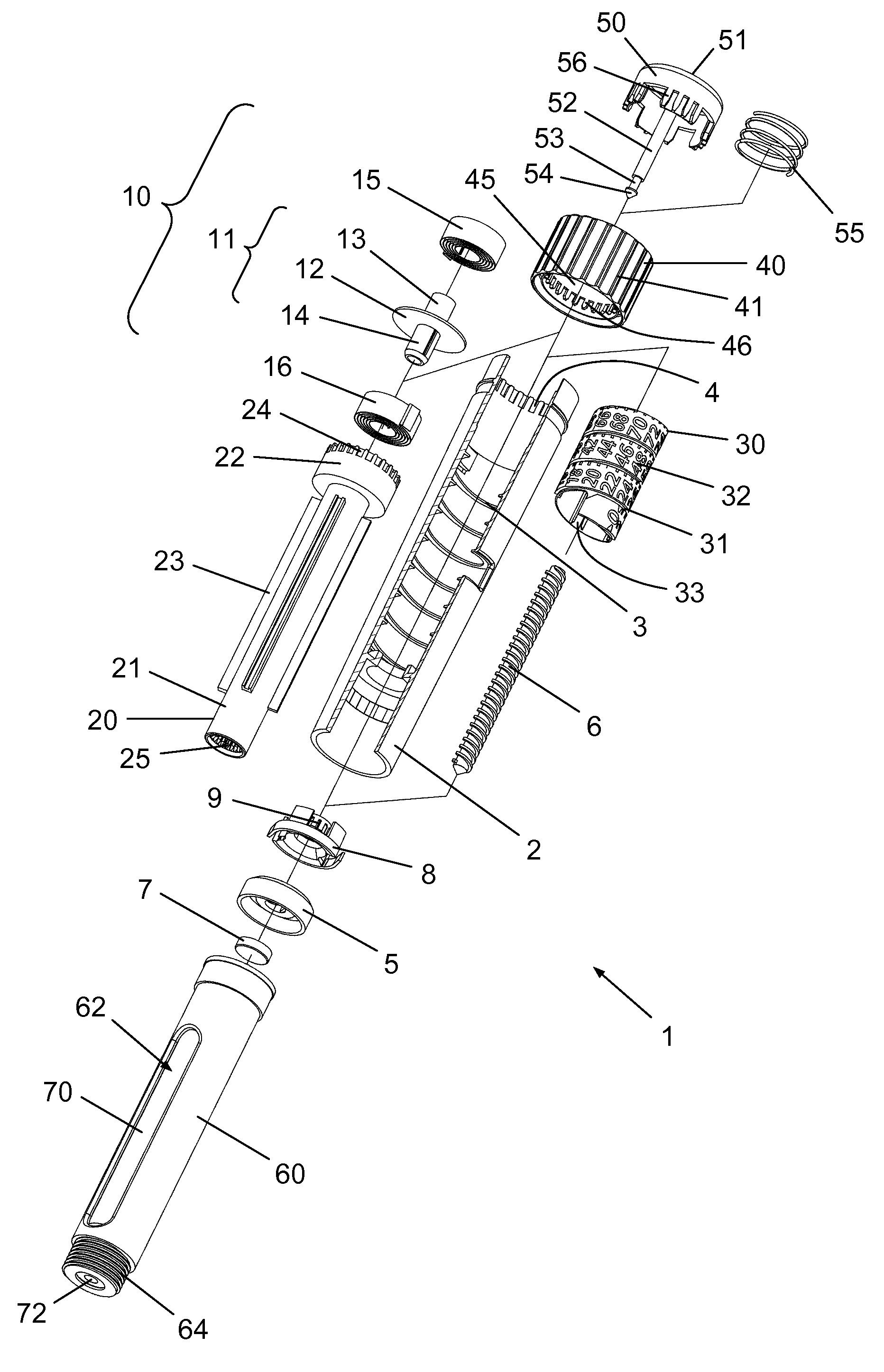
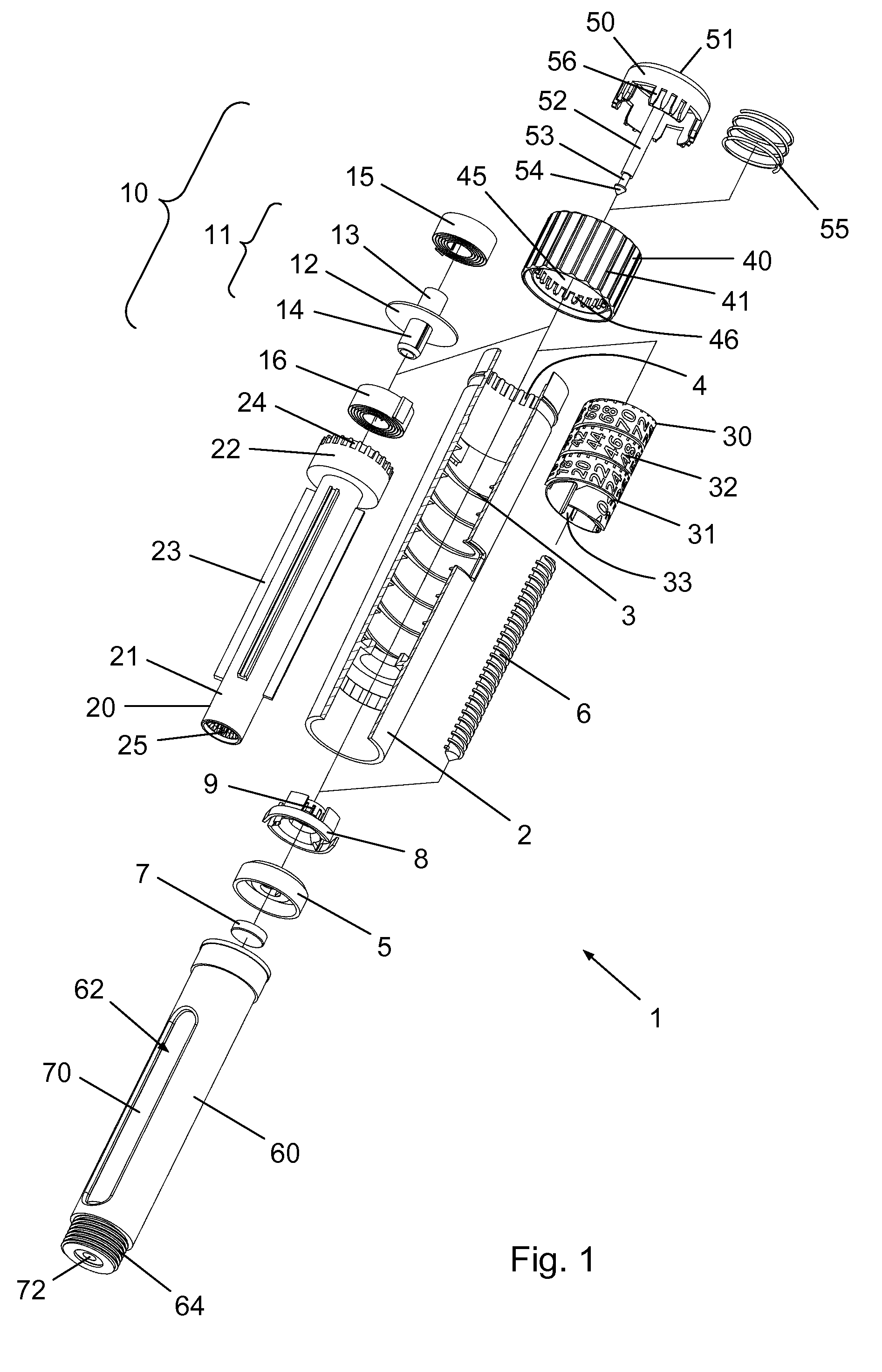
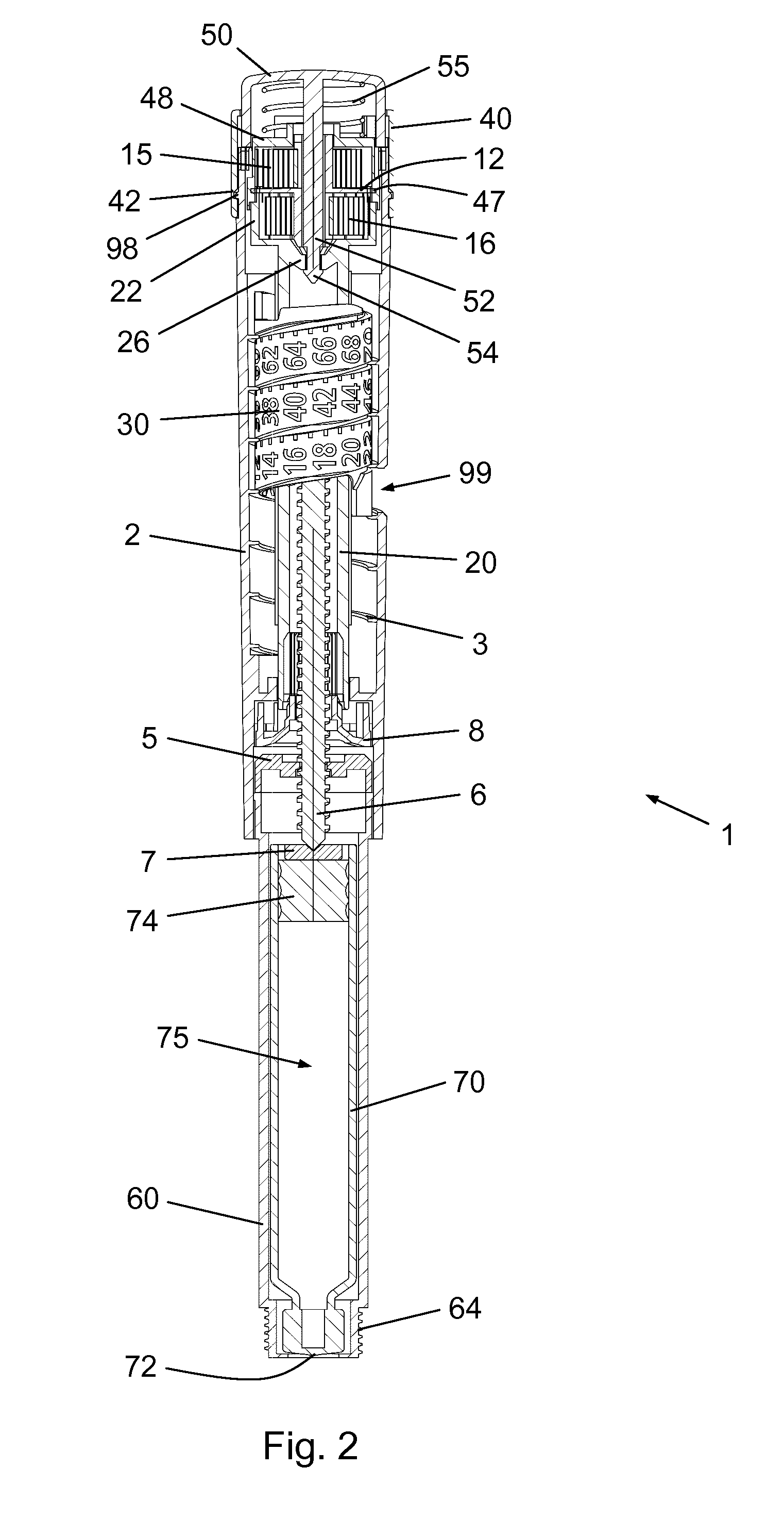
[0061]FIG. 1 shows a pen-type injection device 1 for delivery of a liquid drug substance, such as e.g. insulin or glp-1 for the treatment of diabetes. The injection device 1 comprises a longitudinal housing 2 which defines a general axis. The housing 2 has an interior thread 3 as well as a plurality of spaced apart axial grooves 4 distributed along an inner circumference at its proximal end. A cartridge holder 60 accommodating a cartridge 70 is removably or irremovably attached to the distal end portion of the housing 2, such as e.g. by gluing, snap fitting, bayonet coupling or the like. At its distal...


PUM


Abstract

The present invention relates to a drug delivery device (1) with a power unit (10, 110, 210, 310) adapted to release energy for inducing relative rotation between a first interface portion (45) of the drug delivery device (1) and a second interface portion (22) of the drug delivery device (1). The power unit (10, 110, 210, 310) comprises a first spiral spring member (15, 15, 215, 315) and a second spiral spring member (16, 116, 216, 316) arranged in series along an axially extending structure (11; 111; 211, 285, 281; 311, 385, 1381, 386, 381).

Description

FIELD OF THE INVENTION[0001]The present invention relates to power assisted drug delivery devices, such as e.g. automatic injection devices. The invention also relates to power units useable in such drug delivery devices.BACKGROUND OF THE INVENTION[0002]Drug delivery devices, such as injection devices, are widely used for administration of liquid drugs to people in need of therapeutic treatment. Many injection devices are capable of repeated setting and injection of either a fixed or a variable volume of drug upon operation of respective dose setting and injection mechanisms in the device. Some injection devices are adapted to be loaded with a prefilled drug reservoir containing a volume of drug which is sufficient to provide for a number of injectable doses. When the reservoir is empty, the user replaces it with a new one and the injection device can thus be used again and again. Other injection devices are prefilled when delivered to the user and can only be used until the drug re...

Claims


Application Information

Patent Timeline
Patent Type & Authority Applications(United States)
IPC IPC(8): A61M5/20A61M5/315
CPCA61M5/2033A61M5/31553A61M2005/3126A61M5/31585A61M2005/2026A61M5/31561A61M5/20A61M5/24A61M2005/2407A61M5/31583F16F1/10F16F3/04
Inventor KIILERICH, EBBE
Owner NOVO NORDISK AS
Learn More