
Method for controlling ecm motor to output constant torque

a technology of ecm motor and constant torque, which is applied in the direction of electronic commutation motor control, motor/generator/converter stopper, dynamo-electric converter control, etc., can solve the problems of poor control accuracy and high production cost, and achieve low arithmetic capability, reduce the number of control variables, and simple mathematical models

Active Publication Date: 2015-04-30
ZHONGSHAN BROAD OCEAN
View PDF1 Cites 9 Cited by
  • Summary
  • Abstract
  • Description
  • Claims
  • Application Information

AI Technical Summary

Benefits of technology

The invention provides a method for controlling an electrified control motor to output a constant torque. This method has a simple mathematic model and algorithm, low operational requirements on the CPU, low production costs, and high control accuracy. The method uses experimental means to obtain the function relating to the torque value and a DC bus current, and a microprocessor calculates the target bus current value according to the target torque value. The microprocessor compares the target bus current value with the real-time bus current and regulates the duty cycle of the PWM signal input into the inverter accordingly to achieve the desired constant torque output. This method reduces the number of control variables, simplifies the mathematical model, and allows for the use of low-end CPU or MCU, thereby reducing production costs. The accuracy of the control is effectively ensured through the use of the closed-loop control and full measurements of the experimental means.

Problems solved by technology

A currently used vector control mode has complicate mathematical model, troublesome operation, high demands on the arithmetic capability of a central processing unit (CPU), thereby resulting in high production costs.
A typical constant torque control mode is conducted by scale control of the bus current; however, such a control mode is complicated and has a plurality of variables thereby resulting in poor control accuracy.

Method used


Image

  • Method for controlling ecm motor to output constant torque
  • Method for controlling ecm motor to output constant torque
  • Method for controlling ecm motor to output constant torque

Examples


Embodiment Construction

[0024]For further illustrating the invention, experiments detailing a method for controlling an ECM motor to output a constant torque are described below. It should be noted that the following examples are intended to describe and not to limit the invention.

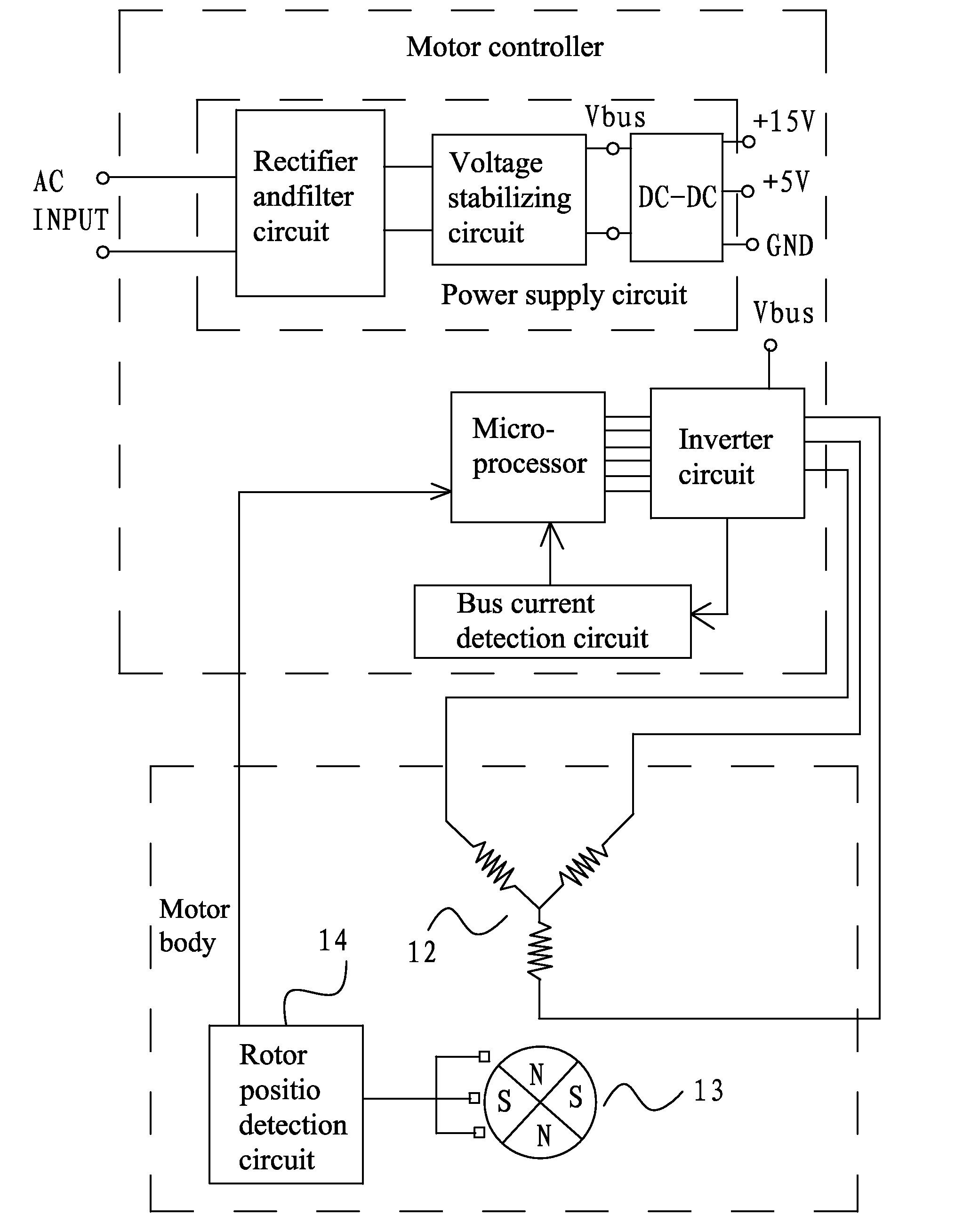
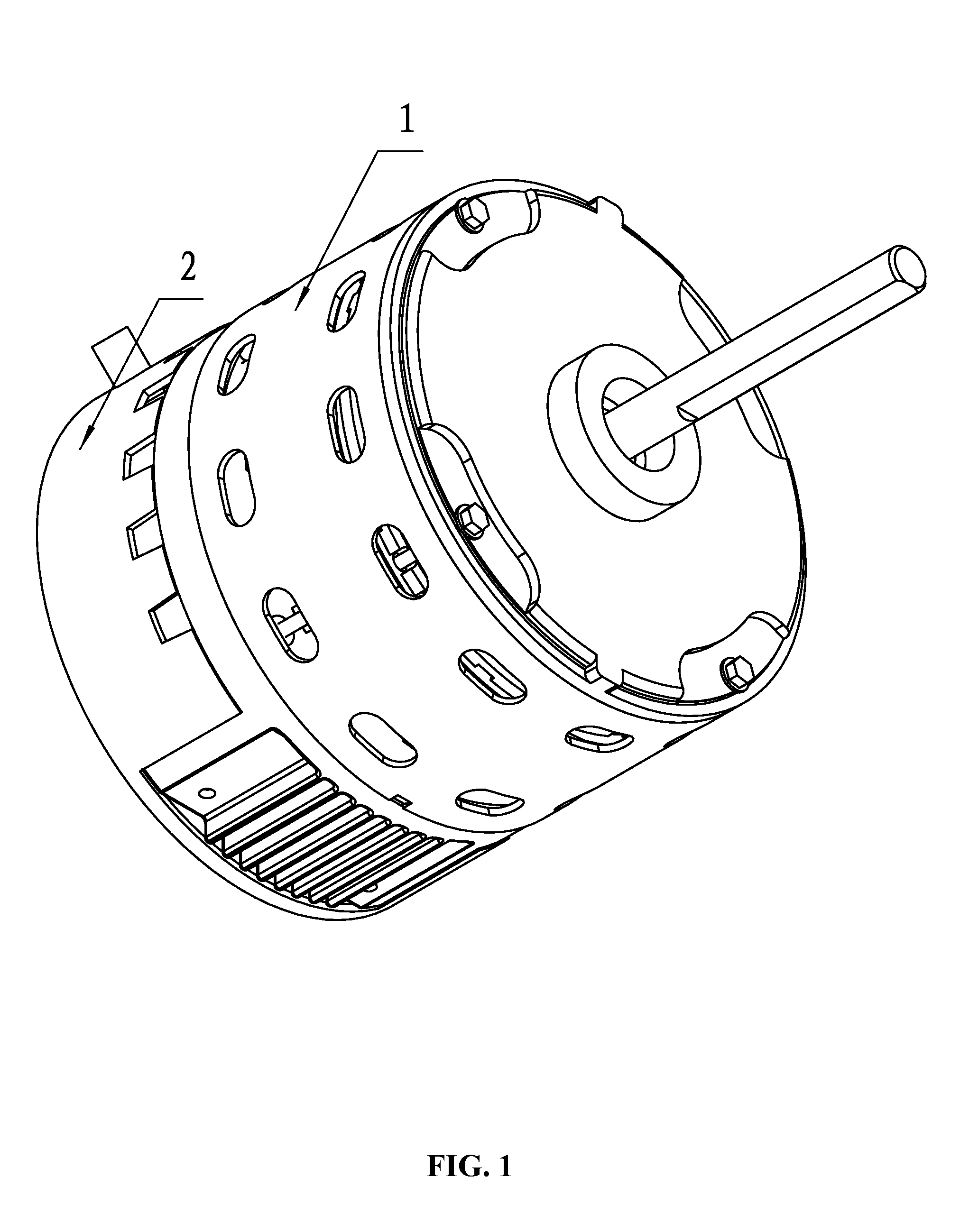
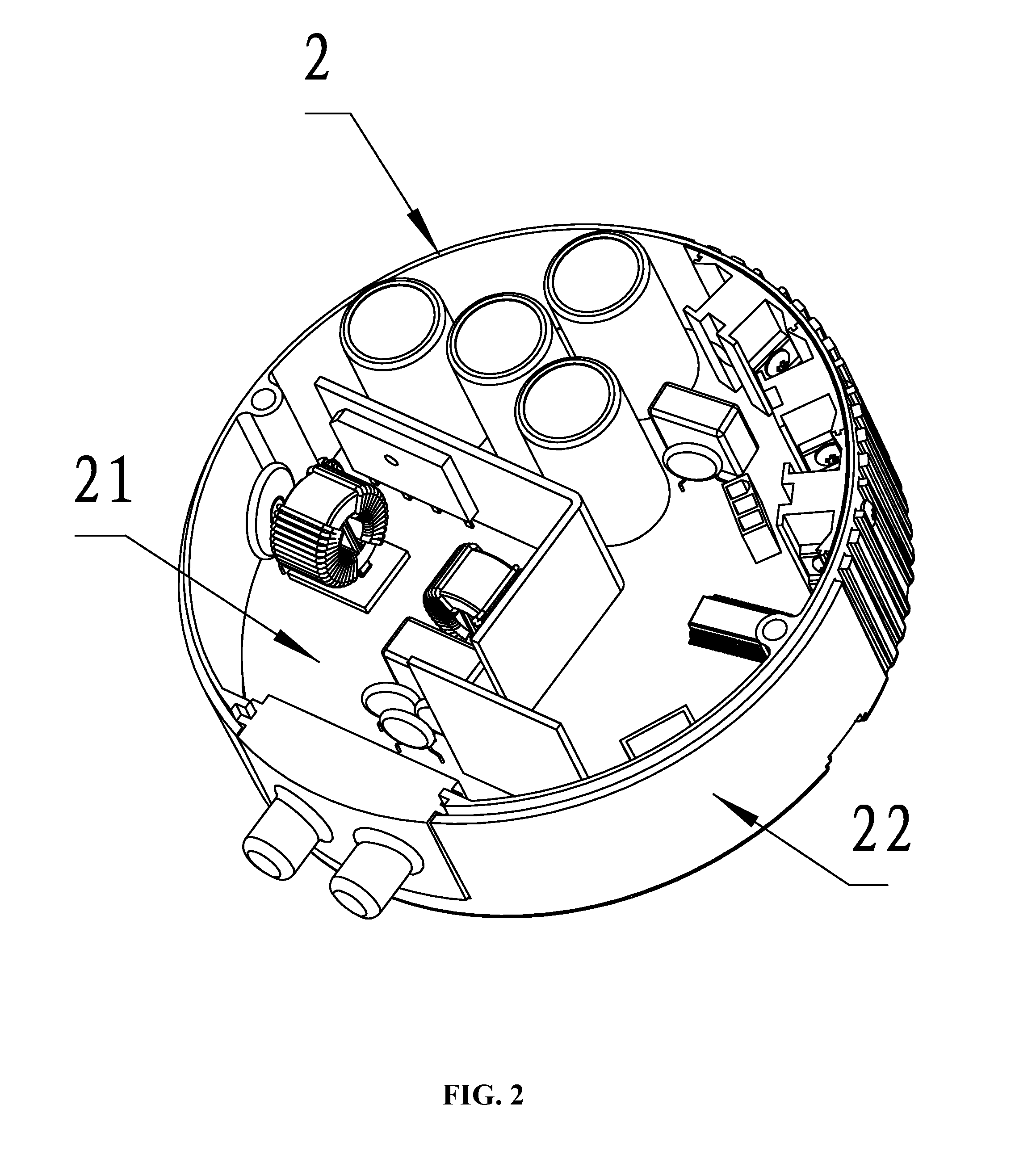
[0025]As shown in FIGS. 1-3, an ECM motor generally comprises a motor controller 2 and a motor body 1. The motor body 1 comprises a stator assembly 12, a rotor assembly 13, and a housing assembly 11. The stator assembly 13 is mounted on the housing assembly 11. The motor body 1 is provided with a hall sensor 14 for detecting a rotor position. The rotor assembly 13 is nested within or outside the stator assembly 12. The motor controller 2 comprises a control box 22 and a control board 21 disposed in the control box 22. The control board 21 generally comprises: a power supply circuit, a microprocessor, a bus current detection circuit, an inverter circuit, and a rotor position detection circuit 14 (the hall sensor). The power supply...


PUM


Abstract

A method for controlling an ECM motor to output a constant torque. The method includes: 1) entering a target torque value T0 from an external device; when the motor is in a non-use state, starting the motor, and allowing the microprocessor to acquire an original output voltage value P chopped by a PWM signal; when the motor is in a running state, allowing the microprocessor to acquire a current output voltage value P chopped by the PWM signal; 2) enabling the microprocessor to calculate a target bus current value Itad using the function Itad=F(T,P) according to the target torque value T0 and the output voltage value P chopped by the PWM signal; and detecting a real-time bus current Ibus; and 3) allowing the microprocessor to compare the target bus current value Itad with the real-time bus current Ibus for conducting a closed-loop control.

Description

CROSS-REFERENCE TO RELATED APPLICATIONS[0001]Pursuant to 35 U.S.C. §119 and the Paris Convention Treaty, this application claims the benefit of Chinese Patent Application No. 201310518422.3 filed Oct. 28, 2013, the contents of which are incorporated herein by reference. Inquiries from the public to applicants or assignees concerning this document or the related applications should be directed to: Matthias Scholl P.C., Attn.: Dr. Matthias Scholl Esq., 245 First Street, 18th Floor, Cambridge, Mass. 02142.BACKGROUND OF THE INVENTION[0002]1. Field of the Invention[0003]The invention relates to a method for controlling an ECM motor to output a constant torque.[0004]2. Description of the Related Art[0005]Electronically commutated motors (ECM) or DC brushless permanent magnet synchronous motors generally have three control modes including a constant rotational speed control mode, a constant torque control mode, and a constant air volume control mode, of which, the constant torque control m...

Claims


Application Information

Patent Timeline
IPC IPC(8): H02P6/08
CPCH02P6/08H02P7/282H02P2205/01H02P27/08H02P6/182
Inventor ZHAO, YONG
Owner ZHONGSHAN BROAD OCEAN
Learn More