System And Method Of Measuring Distances Related To An Object Utilizing Ancillary Objects

Active Publication Date: 2016-01-14
WEXENERGY INNOVATIONS
View PDF1 Cites 39 Cited by
  • Summary
  • Abstract
  • Description
  • Claims
  • Application Information

AI Technical Summary

Benefits of technology

The present invention provides a method of photogrammetric measurement which allows for automation using fiducial patterns on reference and optional ancillary objects. This is accomplished by obtaining a digital image containing the target object, reference object, and one or more ancillary objects, transmitting the image to a server, and receiving the dimension of the target object from the server. A pixel scale factor is calculated based on the measured and known dimensions of the reference object, the one or more ancillary objects, and a corner or edge of the target object in the image. The at least one dimension of the target object is then calculated using the pixel scale factor. This method simplifies the process of estimating the dimension of a target object within a digital image.

Problems solved by technology

While these approaches have shown considerable improvement in building energy efficiency, significant problems prevent more widespread and effective utilization.
Several problems exist in the approaches to minimizing heat transfer through fenestration.
With window films intended for creating an additional “dead air” space adjacent to the window as well as window treatments, accurate measurement of the film dimensions is necessary, often requiring the assistance of a professional with the associated added cost and time.
Other window films, such as tints, infrared or ultraviolet reflective or absorbing films, or low-e films, adhere directly to the windowpane and have similar issues.

Method used


Image

  • System And Method Of Measuring Distances Related To An Object Utilizing Ancillary Objects
  • System And Method Of Measuring Distances Related To An Object Utilizing Ancillary Objects
  • System And Method Of Measuring Distances Related To An Object Utilizing Ancillary Objects

Examples


Embodiment Construction

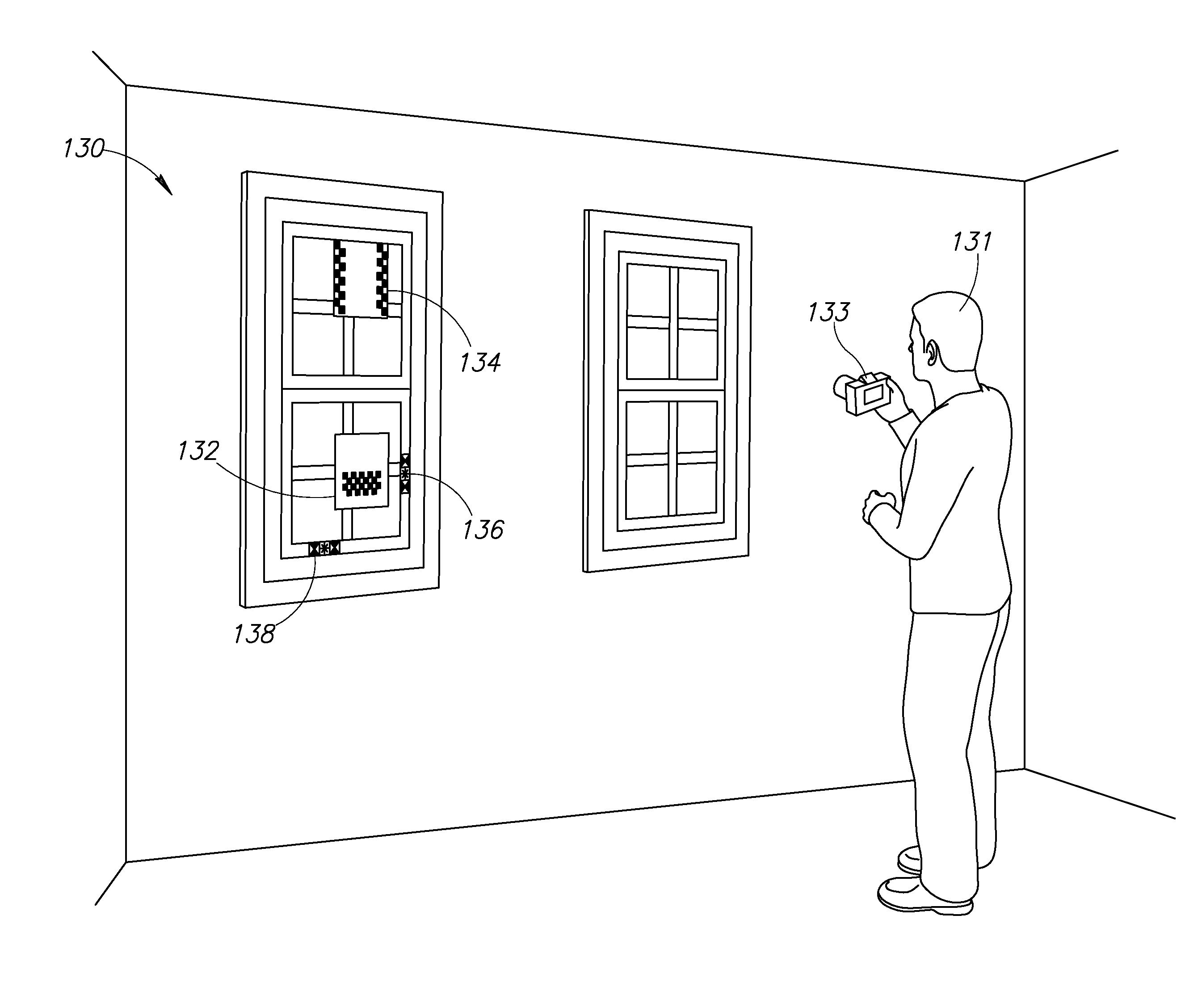
[0045]The present invention provides a system and method for the measurement of distances related to a target object depicted in an image and the construction and delivery of supplemental materials and parts for fenestration. One embodiment of the invention includes a method of photogrammetric measurement in which a digital image is obtained that contains a target object dimension and a reference object dimension in substantially the same plane or line. The digital image then undergoes digital image processing to provide improved measurement capability. In embodiments of the present invention, information regarding a target object, such as fenestration, and its immediate surroundings is provided to an automated or semi-automated measurement process, design and manufacturing system such that customized materials and parts are provided to end users.

[0046]In one method of the present invention, a digital image is obtained that contains at least a portion of an observable constraint dim...


PUM


Abstract

A system and method for measuring distances related to a target object depicted in an image and the construction and delivery of supplemental window materials for fenestration. A captured digital image is obtained containing a scene with a target object whose dimension is to be measured. The digital image may contain a target object dimension identified by one or more ancillary objects and a reference object in the same or different planes. Image processing is performed to find the reference object using known fiducial patterns printed on the reference object, metadata supplied by a user and / or by the detection of colored papers in the scene of the captured image. Adhering objects aid in keeping the reference object applied to an item in the scene such as a wall, while contrast objects aid the image processing to locate the reference object in low contrast reference object / background situations. Once located and measured, the reference object is used to calculate a pixel scale factor used to measure the target object dimensions. Target object dimensions are provided to an automated or semi-automated measurement process, design and manufacturing system such that customized parts are provided to end users.

Description

REFERENCE TO PRIORITY APPLICATION[0001]This application is a continuation-in-part of U.S. application Ser. No. 14 / 320,973, filed Jul. 1, 2014, entitled “System and Method of Measuring Distances Related to an Object,” which is a continuation-in-part of U.S. application Ser. No. 13 / 735,449, filed Jan. 7, 2013, entitled “System and Method of Measuring Distances Related to an Object,” now U.S. Pat. No. 8,923,650, all of which are incorporated herein by reference in their entirety.FIELD OF THE INVENTION[0002]The present invention relates generally to image processing and in particular to a system and method for measuring the distances related to a target object depicted in an image utilizing ancillary objects and the construction and delivery of supplemental window materials for fenestration.BACKGROUND OF THE INVENTION[0003]In recognition of the ecological and cost impact of fossil fuels and other conventional energy sources, significant effort has been expended in developing methods for...

Claims


Application Information

Patent Timeline
IPC IPC(8): G06T7/60G06T7/00
CPCG06T7/602G06T2207/10024G06T7/0044G06T7/62G01C3/00G01C11/04G06T2207/30208
Inventor WEXLER, RONALD M.SPENCE, JOHN P.
Owner WEXENERGY INNOVATIONS
Why Eureka
Try Eureka