
Display panel

a display panel and liquid crystal technology, applied in non-linear optics, instruments, optics, etc., can solve the problems of sealing dissolution, reduce the total time of chemical reaction between liquid crystal molecules and sealants, reduce the effect of affecting the image quality of display panels

Inactive Publication Date: 2016-01-14
INNOLUX CORP
View PDF14 Cites 26 Cited by
  • Summary
  • Abstract
  • Description
  • Claims
  • Application Information

AI Technical Summary

Benefits of technology

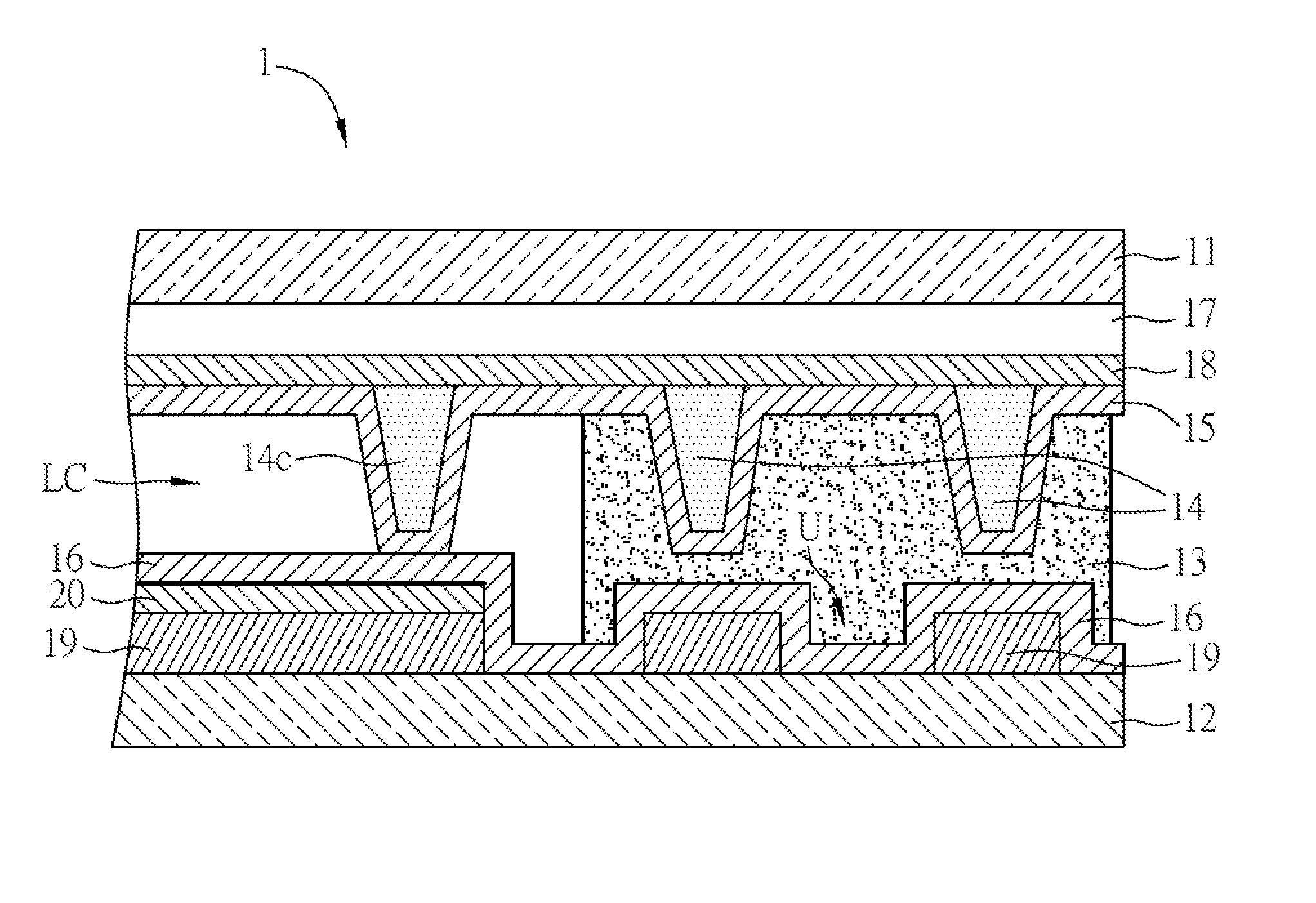
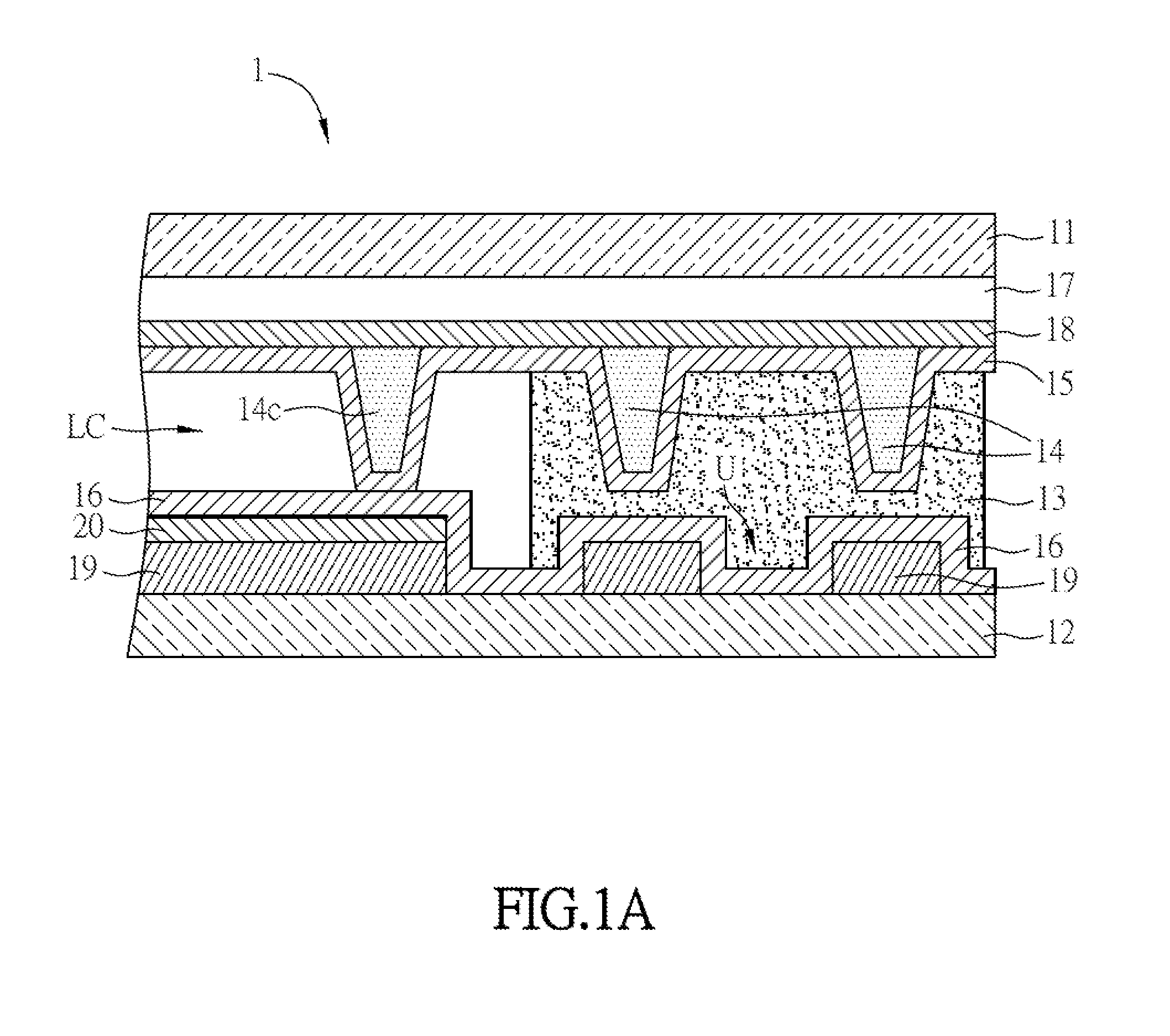
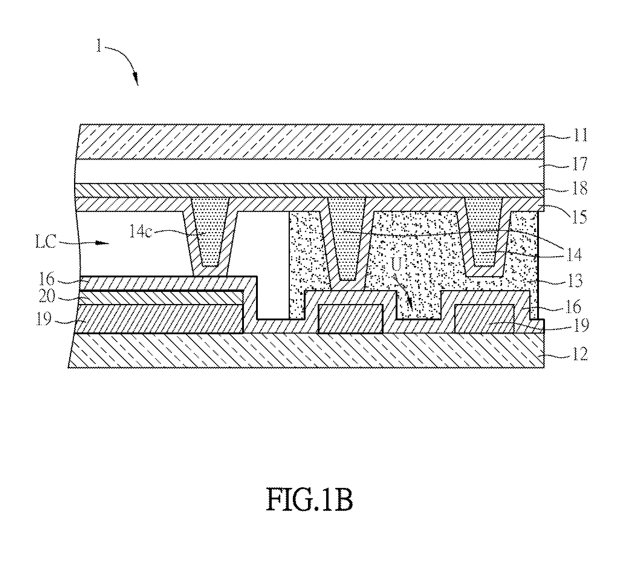
The invention aims to create a display panel that can minimize the issue of Mura occurring in the border region. This is achieved by placing a spacer within the sealant, extending the first alignment layer and second alignment layer to within the sealant, and covering at least part of the spacer with the alignment layers. This arrangement reduces the flow rate of liquid crystal to the sealant, which lowers the chemical reaction between liquid crystal molecules and sealant. As a result, Mura occurring in the border region and affecting the quality of the image display can be minimized.

Problems solved by technology

However, because the sealant has not been cured, the chemical reaction generated between the liquid crystal molecules and the sealant will cause the dissolution of the sealant.
In the worse case, the liquid crystal will be polluted, and therefore the Mura will be generated in the border region of the display device.

Method used


Image

  • Display panel
  • Display panel
  • Display panel

Examples


Embodiment Construction

[0029]The present invention will be apparent from the following detailed description, which proceeds with reference to the accompanying drawings, wherein the same references relate to the same elements.

[0030]FIG. 1A is a schematic sectional diagram of a part of a display panel of an embodiment of the invention.

[0031]As shown in FIG. 1A, the display panel 1 includes a first substrate 11, a second substrate 12, a sealant 13, at least a spacer 14, a first alignment layer 15 and a second alignment layer 16. Besides, the display panel 1 of this embodiment further includes a light blocking layer 17, a first transparent conductive layer 18, a protective layer 19 and a second transparent conductive layer 20.

[0032]The first substrate 11 and the second substrate 12 are disposed oppositely. The first substrate 11 or the second substrate 12 can be made by transparent material, such as glass, quartz or the like, plastic material, rubber, fiberglass or other polymer materials. Otherwise, the firs...


PUM

PropertyMeasurementUnit
transparent conductiveaaaaaaaaaa
transparentaaaaaaaaaa
flow rateaaaaaaaaaa

Abstract

A display panel comprises a first substrate, a second substrate disposed opposite the first substrate, a liquid crystal layer, a sealant, at least a spacer, a first alignment layer and a second alignment layer. The liquid crystal layer is disposed between the first substrate and the second substrate. The sealant seals the periphery of the first substrate and second substrate. The spacer is disposed within the sealant. The first alignment layer is disposed on the first substrate. The second alignment layer is disposed on the second substrate. The first alignment layer or the second alignment layer at least covers partial surface of the spacer.

Description

CROSS REFERENCE TO RELATED APPLICATIONS[0001]This Non-provisional application claims priority under 35 U.S.C. §119(a) on Patent Application No(s). 103123658 filed in Taiwan, Republic of China on Jul. 9, 2014, the entire contents of which are hereby incorporated by reference.BACKGROUND OF THE INVENTION[0002]1. Field of Invention[0003]The invention relates to a display panel and, in particular, to a display panel that can reduce the Mura diffusing from the border region to the display region to affect the quality of the image.[0004]2. Related Art[0005]With the progress of technologies, flat display devices have been widely applied to various kinds of fields. Especially, liquid crystal display (LCD) devices, having advantages such as compact structure, low power consumption, less weight and less radiation, gradually take the place of cathode ray tube (CRT) display devices, and are widely applied to various electronic products, such as mobile phones, portable multimedia devices, noteboo...

Claims


Application Information

Patent Timeline
Patent Type & Authority Applications(United States)
IPC IPC(8): G02F1/1339G02F1/1335G02F1/1337G02F1/1343
CPCG02F1/1339G02F1/133512G02F1/13439G02F1/13394G02F1/1337G02F1/1341
Inventor CHEN, REN-LUNGLEE, HANG-LANGLU, JU-SUNGCHEN, JIAN-CHENG
Owner INNOLUX CORP
Learn More