
Mopa with high-gain solid-state amplifier

a solid-state amplifier and amplifier technology, applied in the direction of instruments, laser details, active medium materials, etc., can solve the problems of limiting the scalability of this prior-art approach, crystal breakage under high power, and degradation of amplified beam quality

Active Publication Date: 2016-01-07
COHERENT SCOTLAND
View PDF5 Cites 4 Cited by
  • Summary
  • Abstract
  • Description
  • Claims
  • Application Information

AI Technical Summary

Benefits of technology

This patent describes a laser device that uses a powerful laser to amplify very small pulses of light. The device includes a special type of crystal that helps to amplify the light pulses and a special optical element that focuses the light onto the crystal. The device also includes a source of pump-radiation that helps to provide the energy needed for the laser to work. The technical effects of this device are that it can produce very high-quality light pulses that can be useful in many different applications.

Problems solved by technology

This caused problems with crystal breakage under high power due to differential absorption.
Furthermore, even at modest levels of amplification, a degradation in the amplified beam quality was often observed, limiting the scalability of this prior-art approach.

Method used


Image

  • Mopa with high-gain solid-state amplifier
  • Mopa with high-gain solid-state amplifier
  • Mopa with high-gain solid-state amplifier

Examples


Embodiment Construction

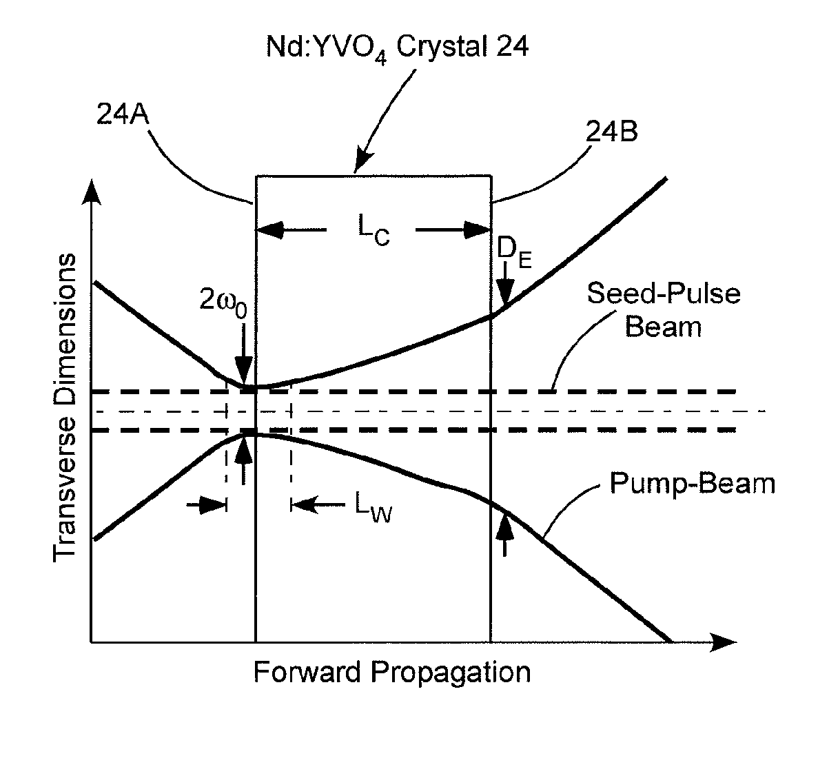
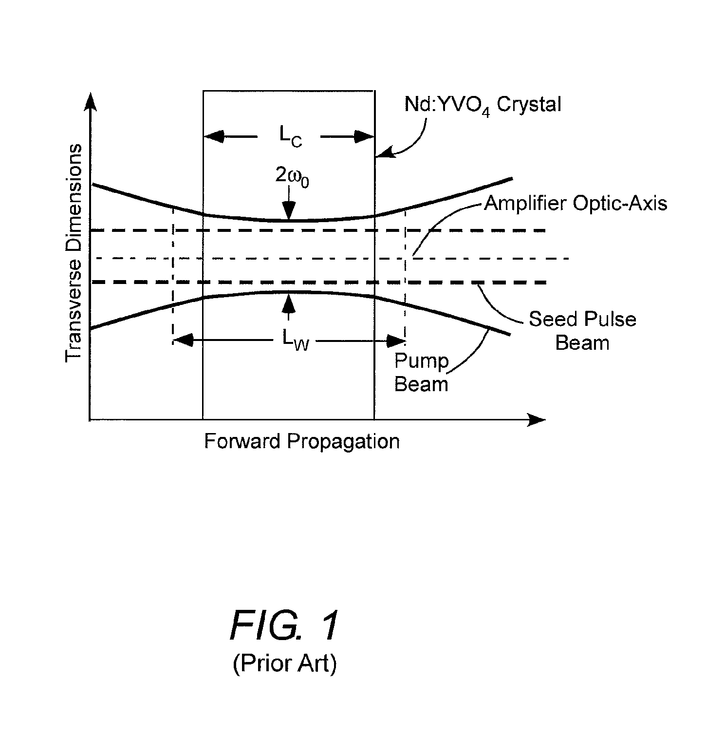
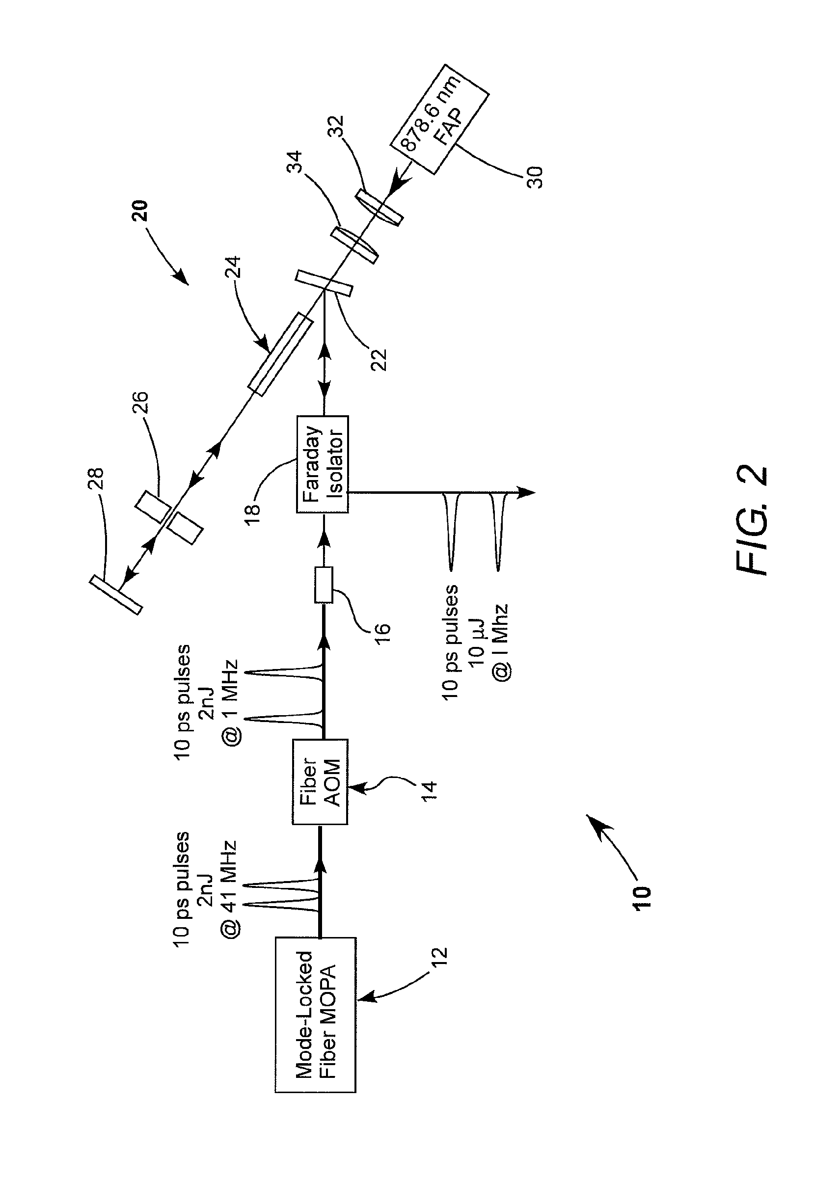
[0017]Referring now to the drawings, wherein like components are designated by like reference numerals, FIG. 2 schematically illustrates a preferred embodiment 10 of MOPA apparatus in accordance with the present invention. In FIG. 2 optical fiber connections between components are depicted by bold solid lines, and free-space beam paths are depicted by fine solid lines.

[0018]Apparatus 10 includes a mode-locked fiber MOPA 12, which is arranged to deliver a first train of optical pulses having a duration of between about 1 ps and 30 ps and a pulse energy of between about 0.5 and about 5 nJ at a repetition frequency (PRF) of between about 10 megahertz (MHz) and 100 MHz. In a preferred example the PRF is 41 MHz and the pulse-energy is about 2 nJ. These pulses are transported to a fiber acousto-optic modulator (AOM) 14, which selectively transmits pulses from the first train thereof to provide a second train of pulses having the same pulse parameters in the first train but at a significan...


PUM


Abstract

Radiation from a VBG-locked diode-laser at a locked wavelength of 878.6 nm is focused into a 30-mm long Nd:YVO4 optical amplifier crystal for optically pumping the crystal (24). The crystal amplifies a beam of seed-pulses from a fiber MOPA (12). The power of pump radiation is about 75 Watts. The radiation is focused into a beam-waist having a minimum diameter of about 600 micrometers. This provides an amplifier having a high gain-factor well over 100. The high-gain factor provides a gain-shaping effect on the seed-pulse beam which overcomes thermal aberrations inherent in such high-power pumping, thereby producing an amplified seed-pulse beam with M2 less than 1.3.

Description

CROSS REFERENCE TO RELATED APPLICATION[0001]This application claims the priority benefit of United Kingdom Patent Application No. GB1411926.7, filed on Jul. 3, 2014, the content of which is incorporated by reference herein in its entirety for all purposes.TECHNICAL FIELD OF THE INVENTION[0002]The present invention relates in general to laser master-oscillator power-amplifier (MOPA) apparatus. The invention relates in particular to a MOPA apparatus including a fiber-laser for generating seed-pulses in a picosecond (ps) range, and a diode-laser pumped (diode-pumped) neodymium-doped yttrium vanadate (Nd:YVO4) solid-state (bulk) amplifier for amplifying the seed-pulses to provide amplified ps pulses having a wavelength of about 1064 nanometers (nm).DISCUSSION OF BACKGROUND ART[0003]MOPA apparatus delivering 1064-nm picosecond pulses is now extensively used for operations such as laser marking. The range of operations that can be addressed by such MOPA apparatus is greater, the greater t...

Claims


Application Information

Patent Timeline
IPC IPC(8): H01S3/11H01S3/06H01S3/091H01S3/16
CPCH01S3/11H01S3/1673G02B27/0927H01S3/0602H01S3/091H01S3/06754H01S3/09415H01S3/1112H01S3/1611H01S3/0085H01S3/2333H01S3/0064H01S3/1022H01S3/0606H01S3/094038H01S3/2308H01S3/2316
Inventor CLUBLEY, DAVIDCUMBERLAND, BURLY
Owner COHERENT SCOTLAND
Learn More