
Wire with corrosion-resistant terminal

a terminal and wire technology, applied in the direction of connection insulation, connection contact member material, coupling device connection, etc., can solve the problems of increasing the size of the wire connecting portion, increasing the difficulty of electrolytic corrosion of the aluminum wire between copper and copper, and increasing the difficulty of electrolytic corrosion of the end parts of the base material. to achieve the effect of reducing the size of the entire terminal

Active Publication Date: 2016-01-07
SUMITOMO WIRING SYST LTD
View PDF2 Cites 2 Cited by
  • Summary
  • Abstract
  • Description
  • Claims
  • Application Information

AI Technical Summary

Benefits of technology

The invention relates to a wire connector that has a coated wire and a metal barrel. The invention includes a special anticorrosive substance that is applied to the wire connection to prevent corrosion and the formation of pits. The anticorrosive substance is applied to a small region near the wire connection, so that it does not increase the size of the connection. The invention also includes a method for crimping the wire barrel to securely hold the wire in place. The technical effect of the invention is to prevent corrosion and pitting between the coated wire and the metal barrel, and to enable the miniaturization of the entire wire connector.

Problems solved by technology

Here, since the terminal is formed by press-working a copper base material, the electrolytic corrosion of the aluminum wire becomes problematic between copper and aluminum if the aluminum wire is used as a wire as described above.
However, since this anticorrosion treatment method is for covering the entire wire connecting portion, the wire connecting portion becomes one size larger.
Thus, electrolytic corrosion more easily occurs on the end parts of the base material where copper is exposed than on parts having the surface covered with the plating.

Method used


Image

  • Wire with corrosion-resistant terminal
  • Wire with corrosion-resistant terminal
  • Wire with corrosion-resistant terminal

Examples


Embodiment Construction

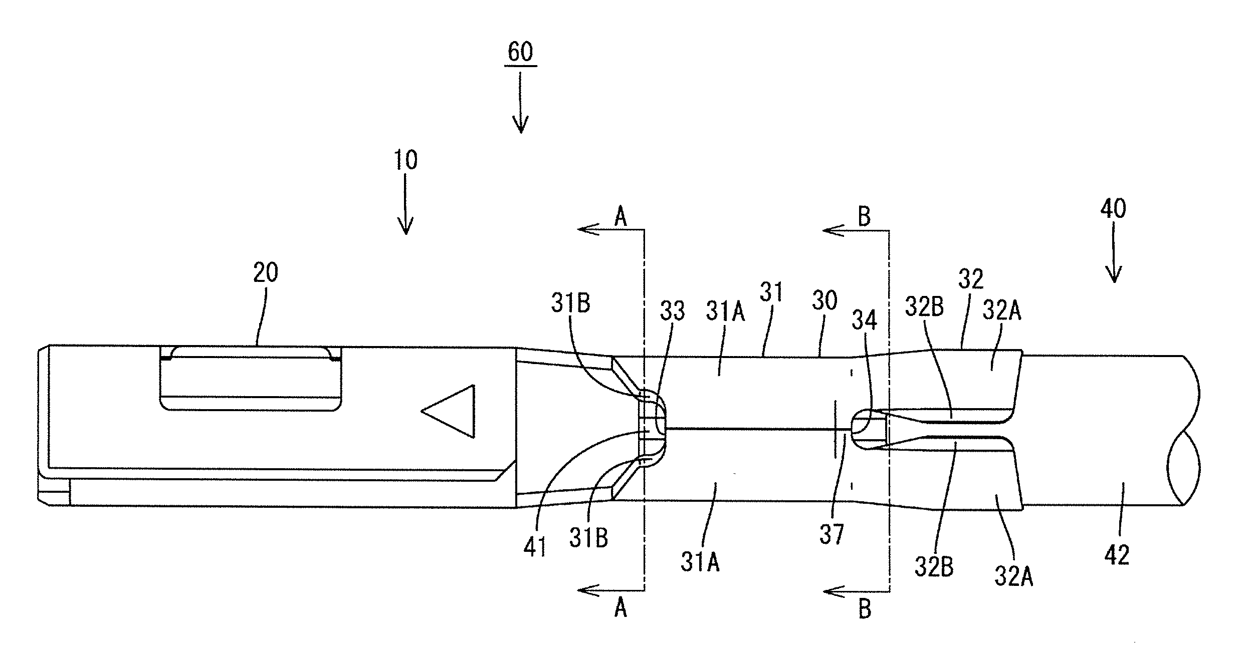
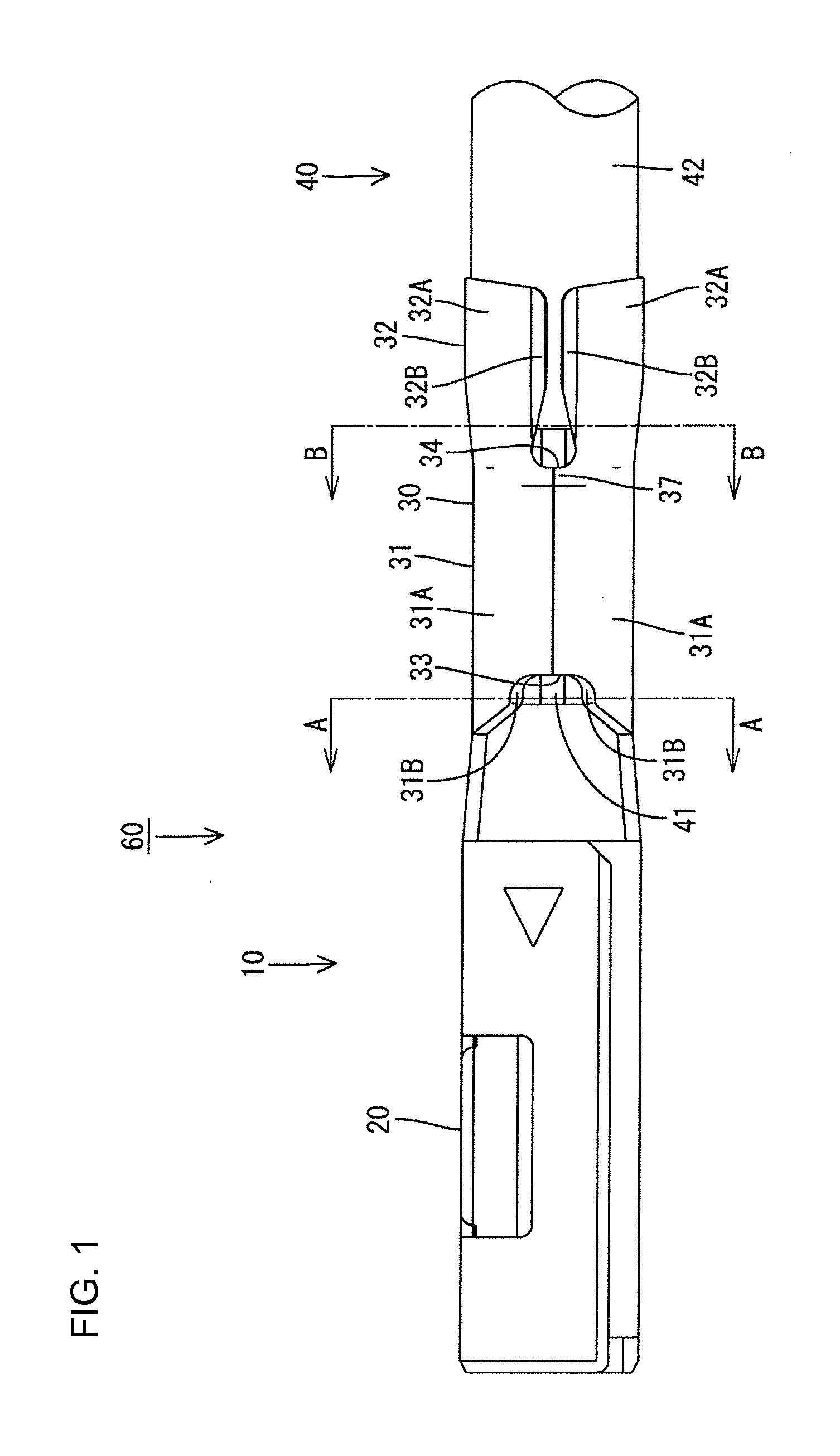
[0032]An embodiment of the present invention is described with reference to FIGS. 1 to 15. A corrosion-resistant terminal 10 in this embodiment includes a terminal connecting portion 20 in the form of a rectangular tube and a wire connecting portion 30 formed behind this terminal connecting portion 20 as shown in FIG. 8. The wire connecting portion 30 is crimped to an end of an aluminum wire 40 as shown in FIG. 1 and an anticorrosive 50 is applied to the wire connecting portion 30 as shown in FIG. 4, whereby an aluminum wire with corrosion-resistant terminal 60 is configured. The anticorrosive 50 is cured by UV irradiation for a predetermined time after being dripped or sprayed in a state of liquid concentrate from above the corrosion-resistant terminal 10.

[0033]The corrosion-resistant terminal 10 is formed by punching out a base material made of copper alloy and applying bending and the like to a punched-out piece. As shown in FIG. 8, the terminal connecting portion 20 is formed in...


PUM


Abstract

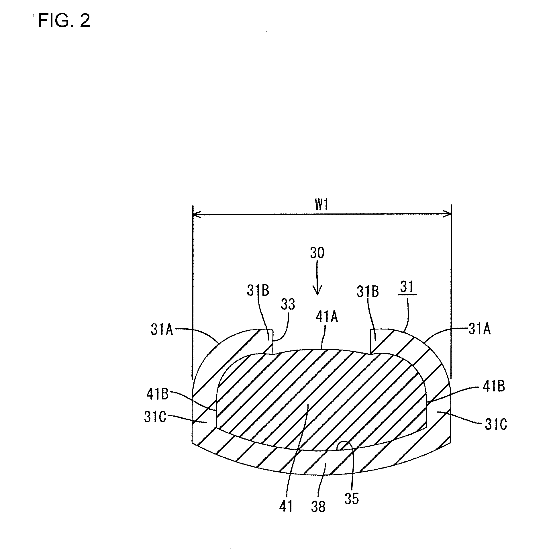
A wire with corrosion-resistant terminal (60) includes an aluminum wire (40) and a corrosion-resistant terminal (10) is formed from a base material made of copper alloy. The terminal (10) includes a wire connecting portion (30) connected to an end of the aluminum wire (40). The copper alloy exposed on an end part of the wire connecting portion (30) is covered with an anticorrosive (50). End parts of the base material in the wire connecting portion (30) face inward on an upper surface of the wire connecting portion (30) while winding around the end of the aluminum wire (40). A storage portion (33, 34) is surrounded by the end parts of the base material, and the anticorrosive (50) is stored in the storage portion (33, 34) in a region (R1, R2) narrower than a maximum width region (W1, W2) on the upper surface of the wire connecting portion (30).

Description

BACKGROUND[0001]1. Field of the Invention[0002]The present invention relates to a wire with corrosion-resistant terminal.[0003]2. Description of the Related Art[0004]In recent years, aluminum wires have been used for the purpose of weight reduction and the like also in the fields of automotive wiring harnesses and the like. In electrically conductively connecting an aluminum wire to a terminal, electrolytic corrosion in which metals are dissolved in the form of ions in moisture and the corrosion of base metals proceeds by an electrochemical reaction is known to occur if a core of the aluminum wire and the terminal are formed of different types of metals, particularly if moisture is present on a contact part of the both. Here, since the terminal is formed by press-working a copper base material, the electrolytic corrosion of the aluminum wire becomes problematic between copper and aluminum if the aluminum wire is used as a wire as described above.[0005]Accordingly, in a wire with ter...

Claims


Application Information

Patent Timeline
IPC IPC(8): H01R13/533H01R4/16H01R4/18
CPCH01R13/533H01R4/18H01R4/16H01R4/62H01R4/188H01R4/185H01R4/70
Inventor MORIKAWA, SATOSHI
Owner SUMITOMO WIRING SYST LTD
Learn More