Eureka AIR delivers breakthrough ideas for toughest innovation challenges, trusted by R&D personnel around the world.

Fluoroscopic pose estimation

a fluoroscopic and pose technology, applied in the field of fluoroscopic pose estimation, can solve the problems of difficult identification with conventional fluoroscopy, ct data is not used in real time, and the fluoroscopic image renders flat 2d images on which it can be somewhat difficult to assess the three-dimensional position of the medical instrumen

Active Publication Date: 2016-01-07
TYCO HEALTHCARE GRP LP
View PDF5 Cites 80 Cited by
  • Summary
  • Abstract
  • Description
  • Claims
  • Application Information

AI Technical Summary

Benefits of technology

The present patent describes a method for registering three-dimensional (3D) computed tomography (CT) image data with two-dimensional (2D) fluoroscopic image data using multiple markers. The method involves searching for the lateral angle and cranial angle of the markers, obtaining a parallel translation and perpendicular translation coordinate, and obtaining a roll angle. The 3D CT image data is then overlaid on the 2D fluoroscopic image data based on the lateral angle, cranial angle, parallel translation, and perpendicular translation coordinate. The method also includes computing the roll angle, determining a performance of the solution, and filtering out unwanted matchings. The technical effect of the patent is to provide a reliable and accurate method for registering 3D CT image data with 2D fluoroscopic image data.

Problems solved by technology

However, the CT data is not used in real time due to the rendering times and the radiation hazard to the users in the vicinity.
Although medical instruments like catheters, biopsy tools, etc., are clearly visible on a fluoroscopic picture, organic features such as soft tissue, blood vessels, suspicious tumor lesions etc., are either somewhat or completely transparent and thus hard to identify with conventional fluoroscopy.
Moreover, fluoroscopic images render flat 2D images on which it can be somewhat challenging to assess three-dimensional position of the medical instrument.
As such, the clinician is not provided all the information that could be desired to visualize the placement of the medical device within the patient's body relative to the area of interest.
Pose estimation methods are known, but such methods have limitations.
For instance, there may be an eventual absence of solution due to non-convergence or the convergence leads to a wrong solution.
Some methods need to use 4 points and there exists geometric constraints on these points, in particular relatively to co-planarity.
There may be a difficulty in debugging failures in an intuitive way.

Method used


Image

  • Fluoroscopic pose estimation
  • Fluoroscopic pose estimation
  • Fluoroscopic pose estimation

Examples


Embodiment Construction

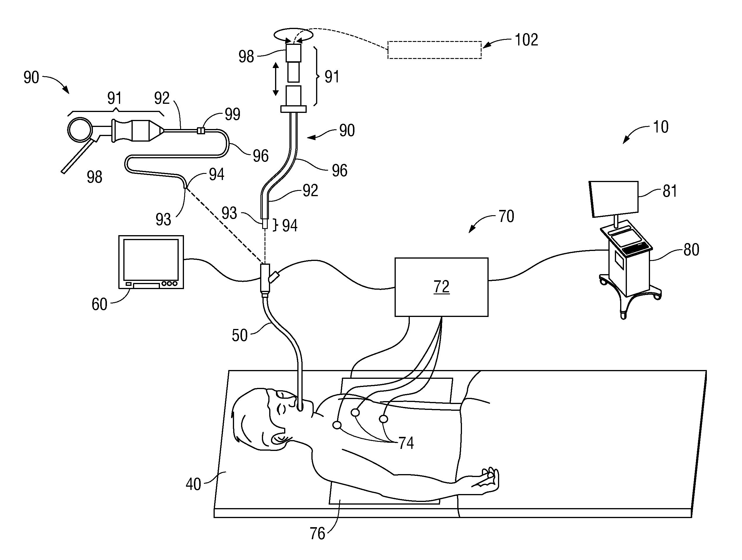
[0031]The present disclosure is related to devices, systems, and methods for finding the fluoroscopic projections relative to 3D CT image data in order to register or overlay portions of the 3D CT image onto a fluoroscopic 2D image. The 2D and 3D data are defined in different referentials and, as such, the rotation angles and translation coordinates between them needs to be computed precisely, in order to exploit both the 3D information from CT images and the precision and real-time character of the 2D fluoroscopic data. The calculations may be based on the coordinates of fiducial markers, measured both in 3D CT and 2D fluoroscopic data. Overlaying portions of the CT image onto a fluoroscopic 2D image may be useful to a user performing an ELECTROMAGNETIC NAVIGATION BRONCHOSCOPY® (ENB) procedure using an electromagnetic navigation (EMN) system.

[0032]An ENB procedure generally involves at least two phases: (1) planning a pathway to a target located within, or adjacent to, the patient'...


PUM


Abstract

Methods and systems for registering three-dimensional (3D) CT image data with two-dimensional (2D) fluoroscopic image data using a plurality of markers are disclosed. In the methods and systems, a lateral angle and a cranial angle are searched for and a roll angle is computed. 3D translation coordinates are also computed. The calculated roll angle and 3D translation coordinates are computed for a predetermined number of times successively. After performing the calculations, the 3D CT image data is overlaid on the 2D fluoroscopic image data based on the lateral angle, the cranial angle, the roll angle, and the 3D translation coordinates.

Description

CROSS-REFERENCE TO RELATED APPLICATIONS[0001]This application claims the benefit of, and priority to, U.S. Provisional Patent Application. No. 62 / 020,250, filed on Jul. 2, 2014, the entire contents of which are incorporated herein by reference.BACKGROUND[0002]1. Technical Field[0003]The present disclosure relates to a system, apparatus, and method of navigation and position confirmation for surgical procedures. More particularly, the present disclosure relates to a system and method of finding fluoroscope projection variables (angles, focal point, zoom, etc.) relative to a CT in order to extract relevant data from the CT and overlay it on a fluoroscopic image.[0004]2. Discussion of Related Art[0005]Visualization techniques related to visualizing a patient's lungs have been developed so as to help clinicians perform diagnoses and / or surgeries on the patient's lungs. Visualization is especially important for identifying a location of a diseased region. Further, when treating the disea...

Claims


Application Information

Patent Timeline
Patent Type & Authority Applications(United States)
IPC IPC(8): G06T7/00G06K9/62G06T11/60G06T15/08G06T19/00
CPCG06T7/0012G06T2219/2016G06T11/60G06T7/0028G06T19/003G06K9/6202G06T2200/04G06T2207/10081G06T2207/10121G06T2207/30204G06T2207/30061G06T2207/30196G06T2210/41G06T2211/428G06T2219/008G06T15/08G06T2207/30016G06T7/33G06T2207/10012
Inventor MERLET, NICOLAS, J.
Owner TYCO HEALTHCARE GRP LP
Why Eureka
Eureka Blog
Learn More