
Methods and systems of enhanced carbon dioxide recovery

a carbon dioxide recovery and carbon dioxide technology, applied in the field of carbon dioxide separation, can solve the problems of large equipment footprint, high energy inefficiency, and large complexity of amine systems, and achieve the effect of enhancing performance characteristics

Active Publication Date: 2016-01-07
APACHE CORPORATION
View PDF5 Cites 5 Cited by
  • Summary
  • Abstract
  • Description
  • Claims
  • Application Information

AI Technical Summary

Benefits of technology

The patent describes a method and system for processing natural gas to remove contaminants, such as carbon dioxide and hydrogen sulfide, using a combination of membrane separation and pressure swing adsorption. The system includes a single stage membrane system that can handle a high volume of natural gas with low purity, a second stage membrane system for improved methane recovery, and a PSA system for concentrating contaminants. The system can produce a high purity natural gas stream with low contaminant levels without the need for additional processes to remove water. The use of membranes and PSA in the system allows for efficient and economic gas processing and contaminant removal. The patent also describes the use of two or more pressure swing adsorption trains to separately purify hydrogen sulfide and carbon dioxide from the membrane system.

Problems solved by technology

While separation processes have their merits, many have inherent disadvantages.
Amine systems can be large and complicated processes that are highly energy inefficient due to high energy requirements for regeneration.
Furthermore, aqueous amines are prone to foaming and are corrosive in nature; often components and piping require stainless steel for construction.
Moreover, with adsorber columns, regenerative columns, flash tanks, reboilers, and water treatment systems, amine systems have a large equipment footprint and are typically not modular in design, making these acid gas removal systems costly and unsuitable for many gas capture applications, such as offshore use.
Therefore in many instances, simple single-stage membrane systems may not be able to achieve the product purity required and / or product recovery is also decreased due to product slippage through the membrane.
Therefore, energy intensive compression, a recycle stream and a second stage of membrane separation is required to reduce product loss.
PSA can achieve excellent purity by adsorbing the target component to be purified, but is usually not appropriate for natural gas separation processes because of the large volumes involved.
PSA is an intrinsically clean technology when compared to amines, which are toxic, can be corrosive, and typically require significant heat input to be regenerated, but ultimately form a waste product.
However, PSA units may not be the best option in streams with very low partial pressures of contaminant gas species.
Existing product recovery systems do not contemplate using PSA for high volume natural gas processing, because there has not been an economical or functional way to use such a system.
However, products of value are wasted because the waste streams of primary separations, such as the permeate byproduct stream of a membrane separation, still contain valuable product, and so too does the waste stream, or “tail gas,” of the PSA used to polish the valuable product stream.
Prior systems have not used PSA to enhance recovery of valuable product lost through the waste stream of a primary separation, such as, for example, a membrane.
Prior systems and methods for purified CH4 recovery have not provided for the joint use of a membrane and PSA to achieve multiple, highly-concentrated product streams.

Method used


Image

  • Methods and systems of enhanced carbon dioxide recovery
  • Methods and systems of enhanced carbon dioxide recovery
  • Methods and systems of enhanced carbon dioxide recovery

Examples


examples

[0083]Simulated examples are presented to illustrate the utility of combining the two disparate techniques (PSA and membrane separation) to achieve enhanced purity and recovery. If processing 100 million standard cubic feet of natural gas per day (MMscfd) with about 13 mol % initial CO2 contamination were required, and only a simple, single-membrane system were used, purified CH4 product is produced, but much of the CH4 also slips into the permeate byproduct gas, or “waste,” stream. And even in a two-stage membrane system with recycle, a better purified product is produced, but a secondary CO2 product is of low purity, with significant higher-value product still slipping into the CO2 product stream. This is also an energy intensive endeavor, because significant compression is required to pressurize the permeate stream in preparation for the inlet to the second membrane unit.

[0084]Referring now to FIG. 8A and Table 1 below, Table 1 shows the values obtained in a simulated single-pass...


PUM

PropertyMeasurementUnit
temperaturesaaaaaaaaaa
pressuresaaaaaaaaaa
partial pressureaaaaaaaaaa

Abstract

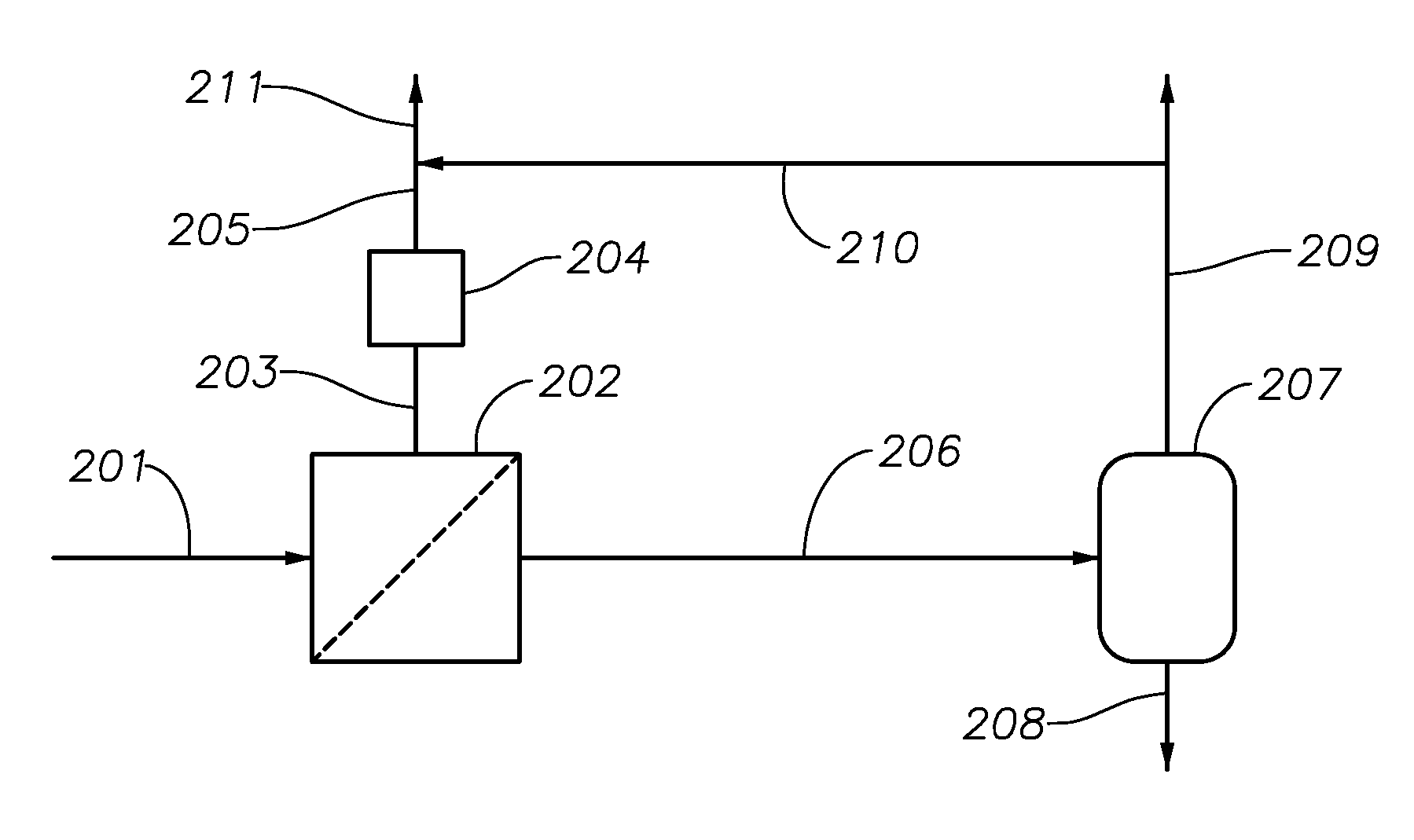
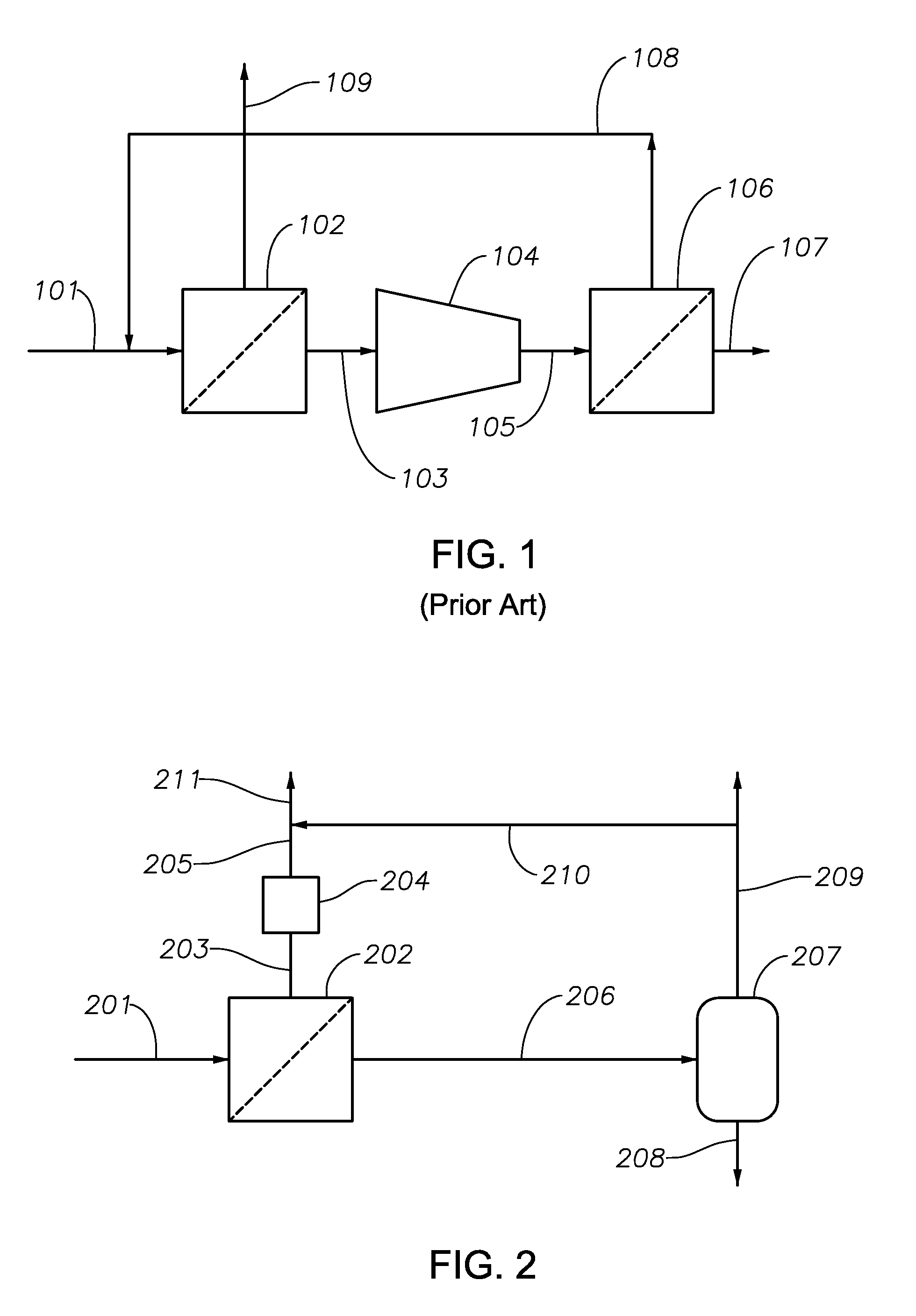
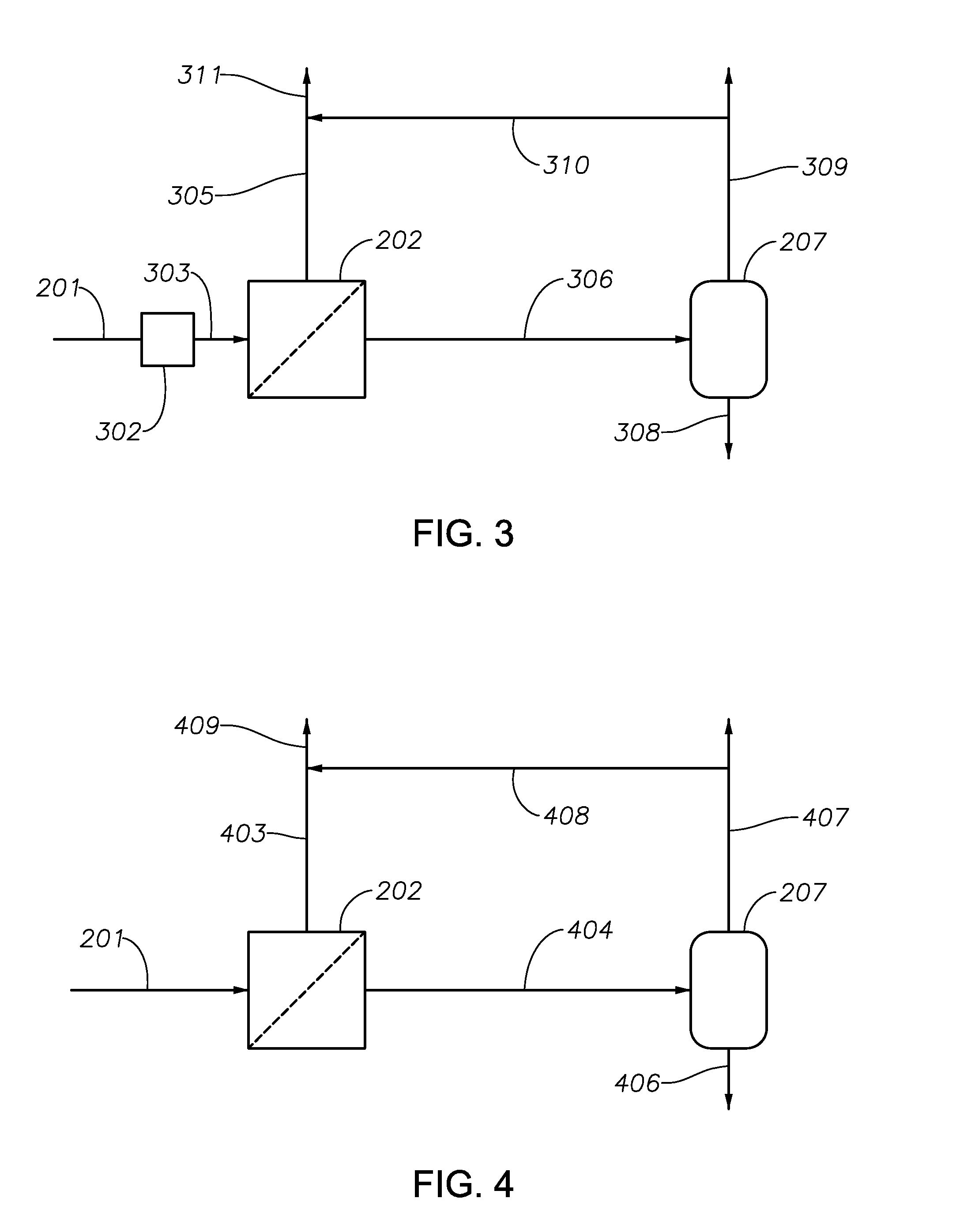
Methods and systems of enhanced carbon dioxide recovery from an inlet gas stream are provided, by introducing the gas stream to one or more membrane-based separation units to produce a permeate byproduct gas stream having increased concentration of carbon dioxide compared to the inlet gas stream and then introducing the permeate byproduct gas stream to one or more pressure swing adsorption units or trains to enhance recovery of hydrocarbons, such as methane, lost in the byproduct stream and to produce a substantially pure carbon dioxide stream, while minimizing process compression and eliminating process heat for process regeneration. The methods introduced herein are for enhancing product recovery by enhancing carbon dioxide recovery from gas streams with pressures greater than atmospheric conditions. Further refinement to the methods would be the introduction of hydrogen sulfide polishing units within the process to produce product that meets or exceeds sales quality specifications.

Description

RELATED APPLIATIONS[0001]This application is a non-provisional application and claims priority to U.S. provisional application Nos. 62 / 081,609 and 62 / 162,924 filed on Nov. 19, 2014 and May 18, 2015, respectively, the full disclosures of which are both hereby incorporated herein by reference in their entireties.BACKGROUND [0002]2. Field[0003]Embodiments of the present invention relate generally to the field of separation of carbon dioxide from a gas stream.[0004]3. Description of Related Art[0005]Carbon dioxide is present in produced natural gas streams and gas streams from oil and gas reserves, especially in gas streams from enhanced oil recovery processes. Carbon dioxide is produced as part of several industrial processes, including but not limited to, hydrocarbon processing plants, other oil, gas, and coal processing plants, and other chemical production plants. Carbon dioxide management can be an essential strategy for these processing and production facilities to achieve environ...

Claims


Application Information

Patent Timeline
Patent Type & Authority Applications(United States)
IPC IPC(8): B01D53/047B01D53/22C01B32/50
CPCB01D53/047C01B31/20B01D53/22B01D2053/221B01D2257/304B01D2256/22B01D53/225B01D2256/245B01D2257/504C10L3/103C10L3/104C10L2290/542C10L2290/548Y02C20/20C01B32/50B01D53/229Y02C20/40Y02P20/151
Inventor HO, JASON G.S.COOPER, J. CALVIN
Owner APACHE CORPORATION
Learn More