
Restoration filter generation device and method, image processing device and method, imaging device, and non-transitory computer-readable medium

a technology of image processing and filter generation, applied in image enhancement, color signal processing circuit, instruments, etc., can solve the problems of image quality being rather degraded and overcorrection, and achieve the effect of preventing overcorrection

Active Publication Date: 2015-12-31
FUJIFILM CORP
View PDF9 Cites 22 Cited by
  • Summary
  • Abstract
  • Description
  • Claims
  • Application Information

AI Technical Summary

Benefits of technology

The invention described in this patent aims to correct the luminance component of image data, but may result in excessive phase overcorrection in a specific color. This can cause image quality degradation and lead to artifacts. By addressing this issue, the invention proposes a method to ensure the phase shift amounts of different colors are balanced and minimize the impact on image quality.

Problems solved by technology

When the phase is overcorrected, an artifact is caused, and image quality may be rather degraded.
A restoration filter with respect to image data subjected to chromatic aberration correction can be generated in the invention described in PTL 3, but there is a problem that overcorrection occurs.

Method used


Image

  • Restoration filter generation device and method, image processing device and method, imaging device, and non-transitory computer-readable medium
  • Restoration filter generation device and method, image processing device and method, imaging device, and non-transitory computer-readable medium
  • Restoration filter generation device and method, image processing device and method, imaging device, and non-transitory computer-readable medium

Examples


first embodiment

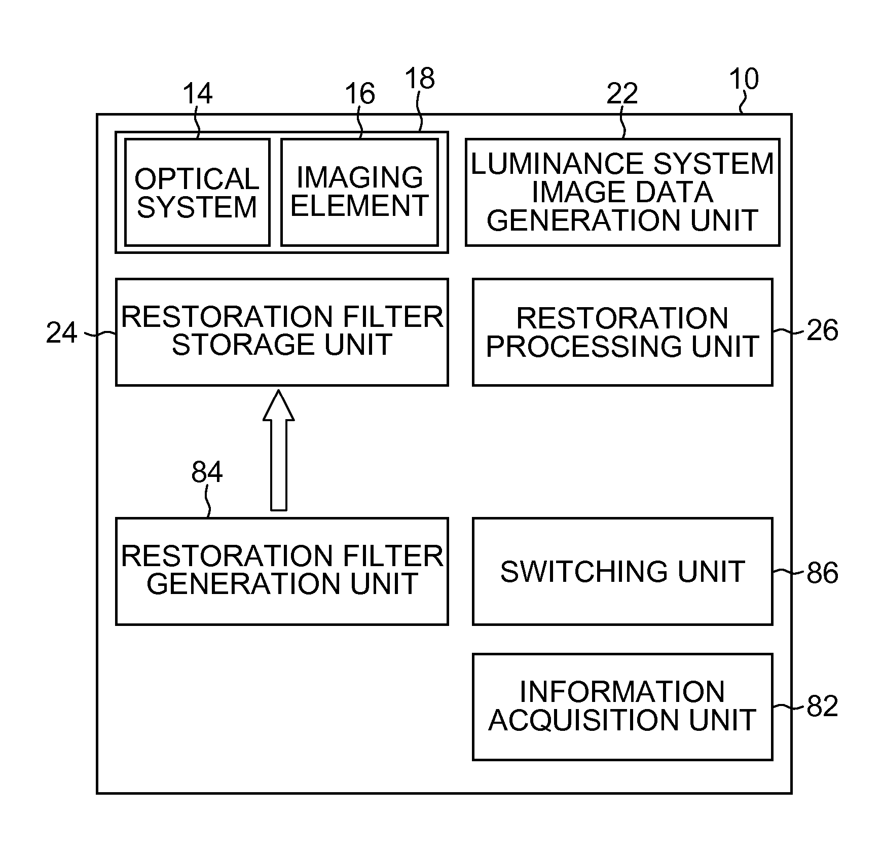
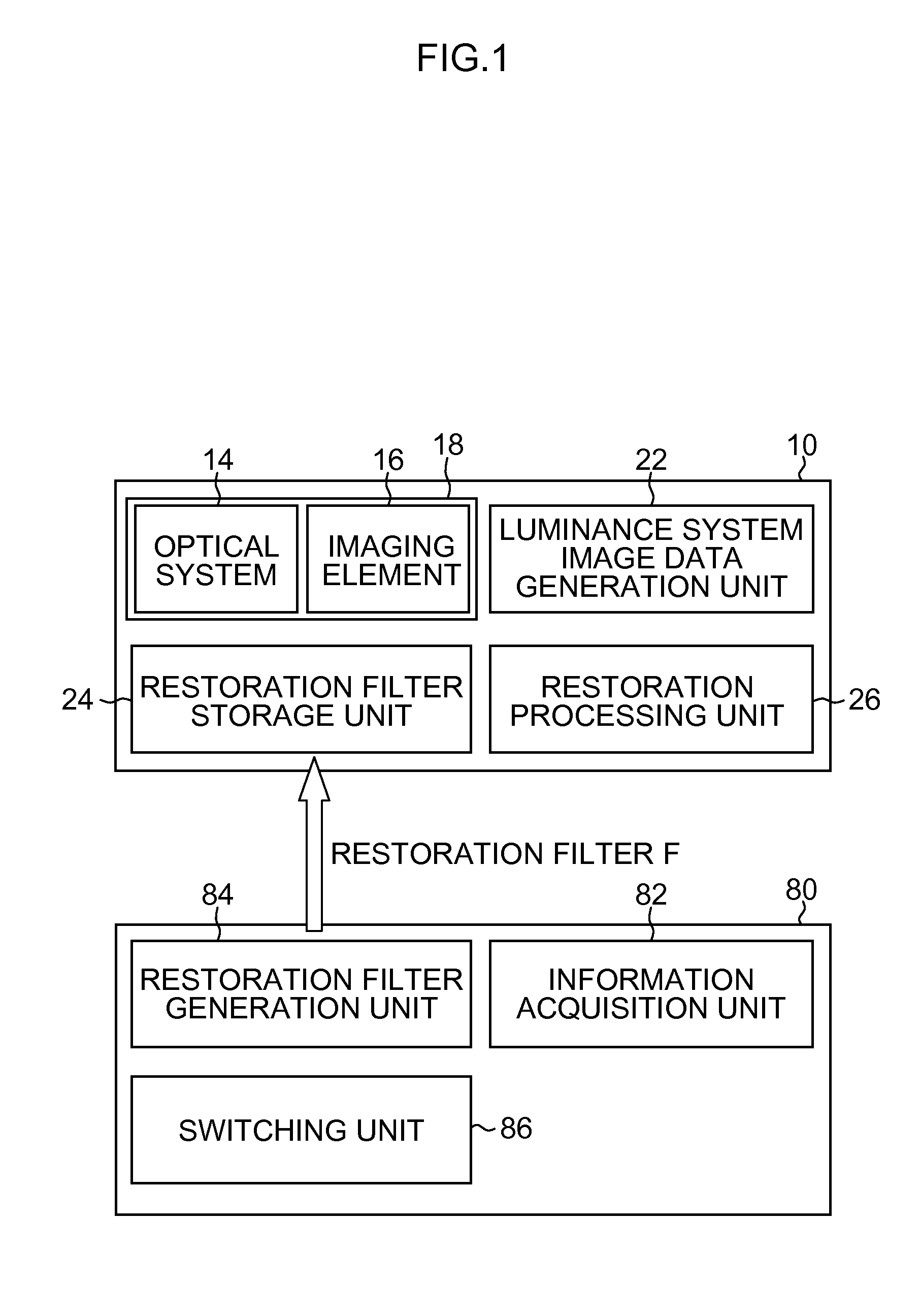
[0089]The restoration filter generation unit 84 in the first embodiment generates a restoration filter that selects a single-color phase shift amount whose absolute value is minimum, from the phase shift amounts of respective colors of multiple colors shown by transfer function information on respective colors of the optical system 14, and corrects the phase shift of luminance system image data by a phase correction amount corresponding to the selected single-color phase shift amount. By this means, a phase shift correction amount is suppressed such that phase correction with respect to the luminance system image data “is not overcorrection” in each color of multiple colors.

[0090]Here, as for “is not overcorrection”, it means that “the absolute value of the phase correction amount that is a phase shift restoration amount does not exceed the absolute value of the phase shift amount”. In the spatial frequency domain, it is preferable that it is not overcorrection in “each color of mul...

second embodiment

[0107]The restoration filter generation unit 84 in the second embodiment includes an operation unit that calculates the filter coefficient of the restoration filter, assuming the number of taps of a restoration filter as an input parameter and assuming the absolute value of the phase correction amount of the restoration filter to be equal to or less than the absolute value of the phase shift amount in an optical system every spatial frequency. By this means, it is possible to surely prevent overcorrection from being caused even in a case where the number of taps is limited.

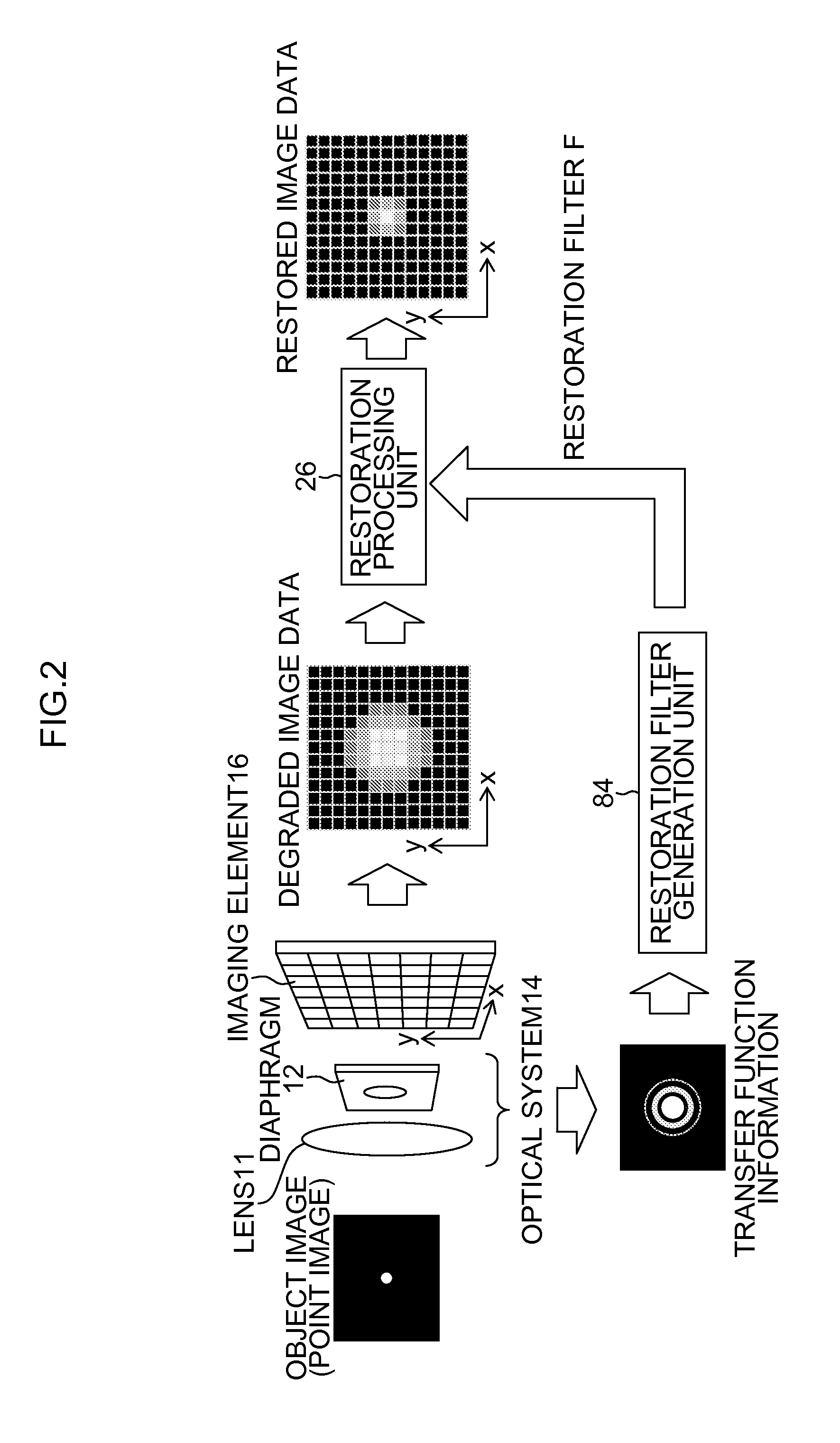
[0108]In the following, a restoration filter generation processing example in a case where the filter coefficient of a Wiener filter is operated as a restoration filter on the basis of a phase transfer function (PTF) in the optical system 14 is specifically described.

[0109]When the number of taps of the restoration filter is assumed as N×N, the filter coefficient of the restoration filter is expressed by matrix C ...

third embodiment

[0122]The restoration filter generation unit 84 in the third embodiment generates a restoration filter that corrects the phase shift of luminance system image data by a phase correction amount corresponding to transfer function information on green (G). The information acquisition unit 82 acquires at least transfer function information on green (G) of multiple colors. The information acquisition unit 82 may acquire only transfer function information on green (G).

[0123]In general, an optical system of an imaging device is designed by attaching importance to green (G) that influences the visual characteristics most among multiple colors (R, G and B). Moreover, the phase shift amount of green (G) tends to be minimum only in a low spatial frequency which is visually important. Therefore, if a restoration filter is generated so as to adequately correct the phase shift amount of green (G) on the basis of only the phase shift amount shown by the transfer function information on green (G), ...


PUM


Abstract

A restoration filter generation device that generates a restoration filter to perform restoration processing on luminance system image data that is image data related to luminance, which is generated based on image data of respective colors of multiple colors obtained by an imaging device having an optical system, includes an information acquisition device acquiring transfer function information corresponding to point image distribution in the optical system, for each color of the multiple colors, and a restoration filter generation device generating the restoration filter based on the transfer function information acquired by the information acquisition device and generating the restoration filter that performs phase correction of the luminance system image data according to the transfer function information on a single color of the multiple colors.

Description

CROSS-REFERENCE TO RELATED APPLICATIONS[0001]This application is a Continuation of PCT International Application No. PCT / JP2013 / 080648 filed on Nov. 13, 2013, which claims priority under 35 U.S.C §119(a) to Japanese Patent Application No. 2013-042186 filed on Mar. 4, 2013. Each of the above application(s) is hereby expressly incorporated by reference, in its entirety, into the present application.BACKGROUND OF THE INVENTION[0002]1. Field of the Invention[0003]The present invention relates to a restoration filter generation device and method that generate a restoration filter to perform restoration processing on luminance system image data generated on the basis of the image data of each color of multiple colors, an image processing device and method that perform restoration processing using this restoration filter, an imaging device including this image processing device, and a program to generate a restoration filter and a non-transitory computer-readable medium.[0004]2. Descriptio...

Claims


Application Information

Patent Timeline
Patent Type & Authority Applications(United States)
IPC IPC(8): G06T5/00H04N9/64H04N9/04G06T5/20H04N1/60H04N23/12
CPCH04N1/409H04N1/58H04N9/04H04N1/6005G06T2207/20024H04N5/217G06T2207/10004G06T5/003G06T5/20G06T5/002H04N9/646G06T2207/10024H04N23/81G06T5/73H04N23/10G06T5/70
Inventor NARUSE, YOUSUKEHAYASHI, KENKICHISUGIMOTO, MASAHIKO
Owner FUJIFILM CORP
Learn More