
Hybrid friction stir welding for dissimilar materials through electroplastic effect

a friction stir welding and dissimilar material technology, applied in welding apparatuses, non-electric welding apparatuses, manufacturing tools, etc., can solve the problems of friction stir welding dissimilar materials in the experimental stage, high axial force when initiating the process, and receiving more and more attention

Active Publication Date: 2015-12-31
RGT UNIV OF MICHIGAN
View PDF3 Cites 2 Cited by
  • Summary
  • Abstract
  • Description
  • Claims
  • Application Information

AI Technical Summary

Benefits of technology

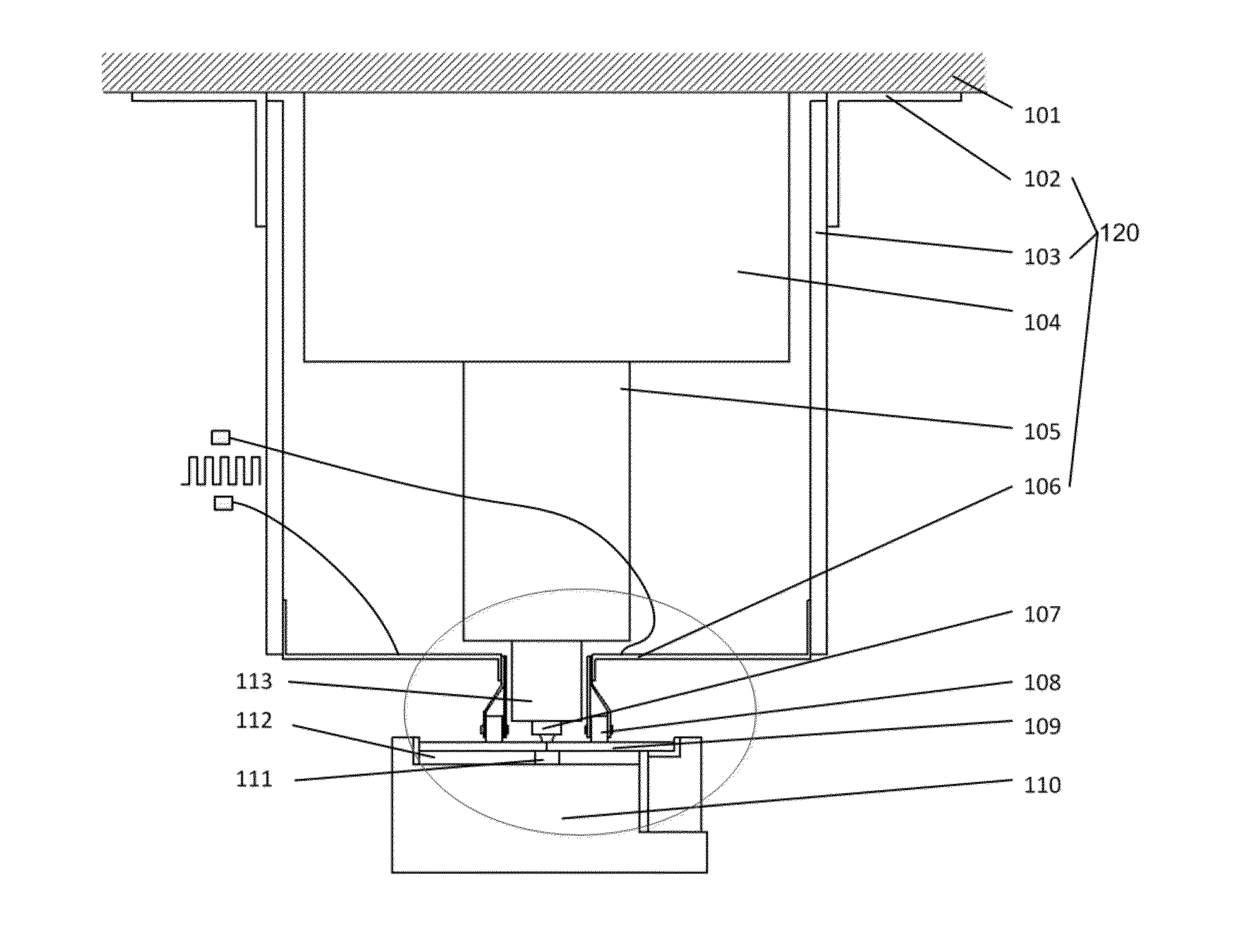
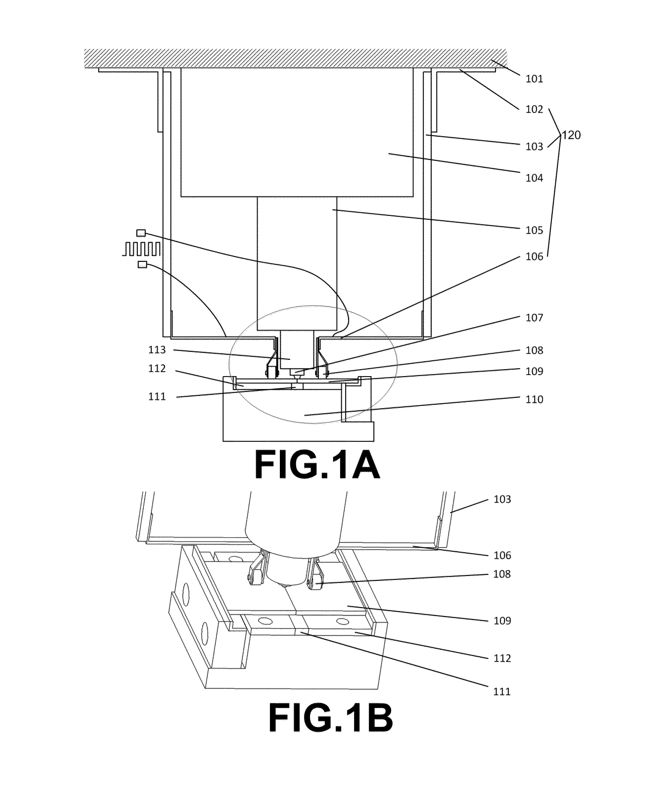
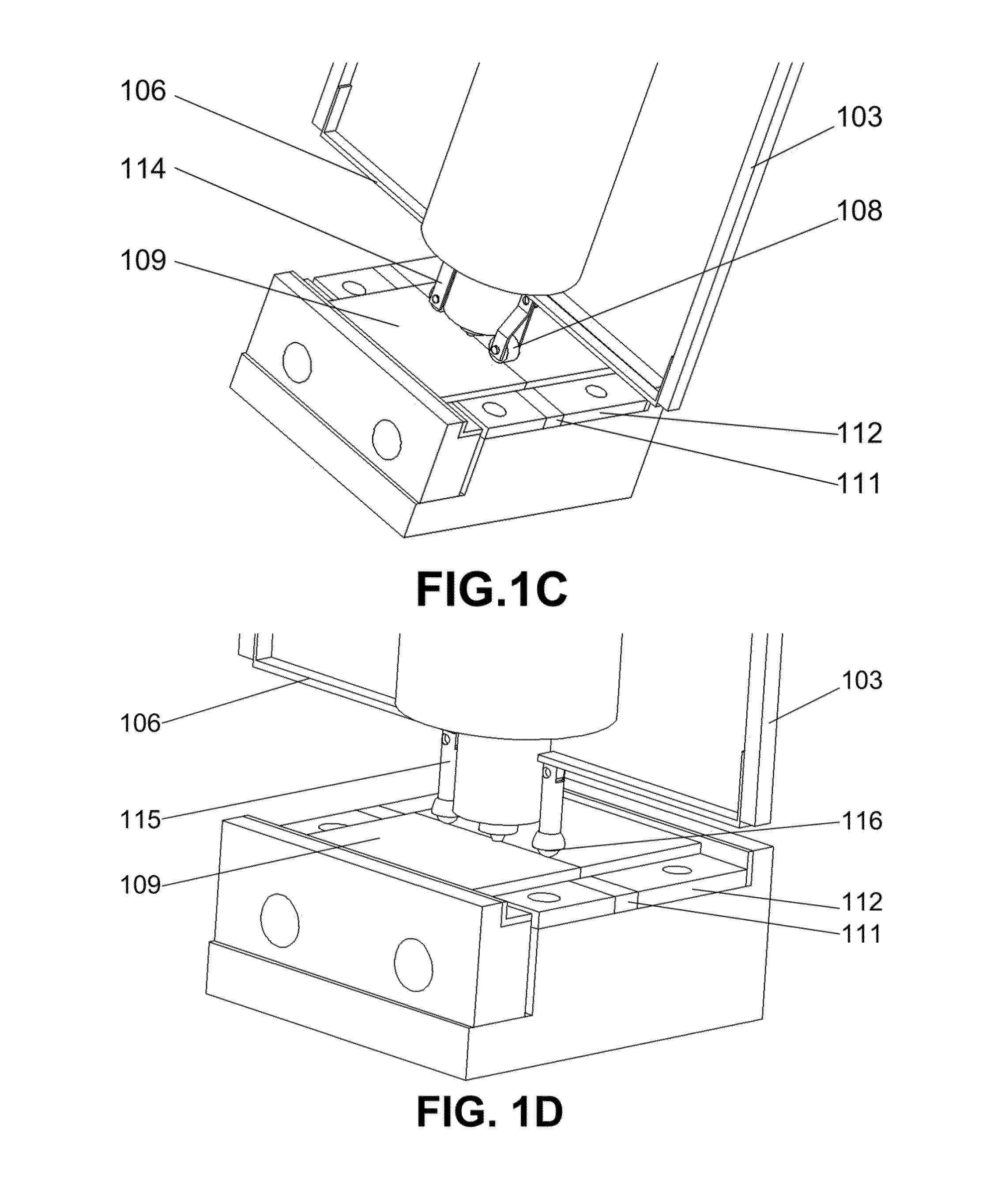
The invention is a method and device for friction stir welding that improves the joint quality and efficiency of dissimilar materials through the use of an electro-Plastic Effect. This method involves using a rotating tool with a pin and shoulder to plasticize the material and create a softening zone around the tool. A current is then applied through conductive wheels or balls to transport the current into the workpiece. The method can be used in existing friction stir welding equipment and can be adjusted based on the layout of the parts being joined. The invention also includes a hybrid friction stir welding device that combines the use of insulation and conductive materials to further improve the joint quality and efficiency of dissimilar materials.

Problems solved by technology

Lightweight vehicles are receiving more and more attention due to the growing concern of energy consumption.
However, friction stir welding dissimilar materials remain in the experimental stage despite its advantages.
Another related drawback is the high axial force when initiating the process and the consequent severe tool wear when welding high melting temperature materials with other relatively softer materials.
However, since the tool is part of the whole circuit, it will also be undesirably heated and results in further tool wear.
Besides, although additional heat sources can help soften the material, they will on the other hand introduce additional heat input and increase the size of heat affected zone, which therefore deteriorate the joint quality.

Method used


Image

  • Hybrid friction stir welding for dissimilar materials through electroplastic effect
  • Hybrid friction stir welding for dissimilar materials through electroplastic effect
  • Hybrid friction stir welding for dissimilar materials through electroplastic effect

Examples


Embodiment Construction

[0022]Example embodiments will now be described more fully with reference to the accompanying drawings.

[0023]Example embodiments are provided so that this disclosure will be thorough, and will fully convey the scope to those who are skilled in the art. Numerous specific details are set forth such as examples of specific components, devices, and methods, to provide a thorough understanding of embodiments of the present disclosure. It will be apparent to those skilled in the art that specific details need not be employed, that example embodiments may be embodied in many different forms and that neither should be construed to limit the scope of the disclosure. In some example embodiments, well-known processes, well-known device structures, and well-known technologies are not described in detail.

[0024]The terminology used herein is for the purpose of describing particular example embodiments only and is not intended to be limiting. As used herein, the singular forms “a,”“an,” and “the” ...


PUM

PropertyMeasurementUnit
Temperatureaaaaaaaaaa
Lengthaaaaaaaaaa
Densityaaaaaaaaaa

Abstract

A hybrid Friction Stir Welding approach and device for dissimilar materials joining employing Electro-Plastic Effect. The approach and device include an introduction of high density, short period current pulses into traditional friction stir welding process, which therefore can generate a localized softened zone in the workpiece during plastic stirring without significant additional temperature increase. This material softened zone is created by high density current pulses based on Electro-Plastic Effect and will move along with the friction stir welding tool. Smaller downward force, larger processing window and better joint quality for dissimilar materials are expected to be achieved through this hybrid welding technique.

Description

CROSS-REFERENCE TO RELATED APPLICATIONS[0001]This application claims the benefit of U.S. Provisional Application No. 62 / 017,286, filed on Jun. 26, 2014. The entire disclosure of the above application is incorporated herein by reference.GOVERNMENT INTEREST[0002]This invention was made with government support under DE-PI0000012 awarded by the Department of Energy. The Government has certain rights in the invention.FIELD[0003]The present disclosure relates to a hybrid Friction Stir Welding (FSW) approach and device for joining dissimilar materials employing Electro-Plastic Effect.BACKGROUND AND SUMMARY[0004]This section provides background information related to the present disclosure which is not necessarily prior art. This section provides a general summary of the disclosure, and is not a comprehensive disclosure of its full scope or all of its features.[0005]Lightweight vehicles are receiving more and more attention due to the growing concern of energy consumption. Gradual applicati...

Claims


Application Information

Patent Timeline
IPC IPC(8): B23K20/12B23K31/02B23K20/06
CPCB23K20/1245B23K20/126
Inventor LIU, XUNLAN, SHUHUAINI, JUN
Owner RGT UNIV OF MICHIGAN
Learn More