
Free end spinning machine piecing trolley

A technology of spinning machine and free end, which is applied in the field of piecing trolley of free-end spinning machine, which can solve the problems of large amount of labor and the limitation of rotor speed, so as to improve the efficiency of piecing, reduce the workload of manpower, improve the success rate of piecing and The effect of joint quality

Active Publication Date: 2015-09-16
ZHEJIANG RIFA TEXTILE MASCH CO LTD
View PDF11 Cites 0 Cited by
  • Summary
  • Abstract
  • Description
  • Claims
  • Application Information

AI Technical Summary

Problems solved by technology

[0003] The purpose of the present invention is to overcome the shortcomings of the existing semi-automatic rotor spinning machine, which has a large amount of labor and the speed of the rotor is limited during jointing, and to provide a free end that can realize high-quality automatic jointing at a relatively high rotor speed. Spinning semi-automatic piecing trolley

Method used


Image

  • Free end spinning machine piecing trolley
  • Free end spinning machine piecing trolley

Examples


Embodiment Construction

[0012] Specific embodiments of the present invention will be described in detail below in conjunction with the accompanying drawings.

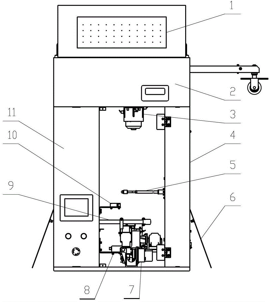
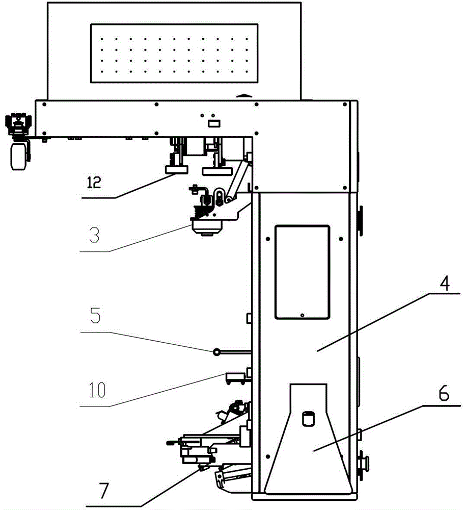
[0013] like Figure 1~2 As shown, the present invention includes a frame 4, a driving device, a positioning device 3, an automatic splicing device 7, a rotor speed measuring device 8, a lifting device 5, a yarn storage device 9, a communication device 10, an electric control system 2, and a blowing and sucking device 11 and the human body induction device 6, the frame 4 includes a horizontal part and a vertical part; the driving device is installed on the frame horizontal part, including a power mechanism 1 and a moving mechanism 12 connected by transmission, the moving mechanism 12 is mainly composed of rollers, and the moving mechanism 12 Press against the traveling track of the trolley on the main machine of the spinning machine, mount the jointing trolley on the traveling track of the trolley, and drive the jointing trolley to tour through...


PUM


Abstract

The invention discloses a free end spinning machine piecing trolley, belonging to the technical field of free end spinning. The traditional semi-automatic rotor spinning machine has the disadvantages that the piecing workload is large, and the rotate speed of a rotor during piecing is limited. The free end spinning machine piecing trolley comprises a stand, a drive device, an automatic piecing device, a rotor speed measurement device, a lifting device, a yarn storage device, a communication device, an electric control system and a positioning device, wherein the drive device is installed at the transverse part of the stand, the automatic piecing device, the rotor speed measurement device, the lifting device, the yarn storage device, the communication device, the electric control system and the positioning device are installed at the vertical part of the stand. The automatic piecing device comprises a cotton feeding control mechanism and a yarn drawing mechanism which are installed on a slide seat, the slide seat is movably installed on a base and is connected with a slide seat drive mechanism, the lifting device comprises a swing link and a swing link drive mechanism, the yarn storage device comprises a fan, a wind suction pipe and a yarn storage pipe, and the electric control system is connected with the drive device, the positioning device, the automatic piecing device, the communication device, the rotor speed measurement device, the lifting device and the fan. With the adoption of the free end spinning machine piecing trolley, under high rotate speed of the rotor, the piecing success rate is increased, and the piecing quality is improved.

Description

technical field [0001] The invention belongs to the technical field of free-end spinning, and in particular relates to a joint trolley of an open-end spinning machine. Background technique [0002] Open-end spinning, that is, rotor spinning technology, is a new spinning technology. During the spinning process, it is inevitable that there will be yarn breakage. After the breakage, it needs to be re-jointed until the package size reaches the set requirement. At present, semi-automatic rotor spinning machines are used in large quantities on the market, and semi-automatic piecing devices are used. The semi-automatic piecing device is installed on the main frame of the spinning machine, one for each spindle. Using the semi-automatic piecing device requires manual assistance to complete the piecing process. The piecing process is as follows: first raise the creel to separate it from the winding roller, stop the winding rotation, manually find the end of the yarn on the package...

Claims


Application Information

Patent Timeline
Patent Type & Authority Patents(China)
IPC IPC(8): D01H4/48
Inventor 吕永法徐剑锋
Owner ZHEJIANG RIFA TEXTILE MASCH CO LTD
Learn More