
Laser with sub-wavelength hole array in metal film

a metal film, sub-wavelength technology, applied in the direction of laser details, active medium materials, optical resonator shape and construction, etc., can solve the problems of high metal loss, unidirectional propagation, physical dimensions and optical mode volume affected by diffraction limit,

Inactive Publication Date: 2015-12-17
PURDUE RES FOUND INC
View PDF4 Cites 12 Cited by
  • Summary
  • Abstract
  • Description
  • Claims
  • Application Information

AI Technical Summary

Benefits of technology

This patent describes a way to create a small optical laser using sub-wavelength size holes embedded in a thin metal film. The device can be tuned for different technologies by changing the arrangement of holes, the size, thickness, and shape of holes, as well as the direction of signal emission, and the composition and positioning of the optically active media. The device can emit light in visible, infrared, and other wavelength ranges and can be used in various industries such as electronics, sensors, and biomedical applications.

Problems solved by technology

However, in contrast to dielectric cavities, the high losses inherent in the metal are impeding the development of such laser devices.
However, in conventional lasers, the cavity is loaded by dielectric media, and thus the physical dimensions and optical mode volume are affected by the diffraction limit.
The diffraction limit restrains the footprints of the photonic devices to be on the wavelength scale and prevents them from being integrated with electronic devices.
Various schemes have been attempted to achieve lasing using plasmonic cavities in the visible wavelength region with unidirectional propagation, but they have not been successful.
Several fabrication limitations exist.
However, commercial laser dyes are rarely compatible with this method due to the absence of functional groups for covalent bonding.
Second, the chemical approach requires stringent fabrication skills to achieve a doping concentration sufficient to compensate plasmon losses.
Third, the spectral position of the plasmonic mode in a spherical metal structure is difficult to tune when optimizing the energy transfer from the gain medium to the metal.
This is especially troublesome if other gain materials with different emission lines are to be incorporated into a nanolaser design.
In addition, the core-shell nanoparticle is incapable of producing unidirectional laser emission.
In that case, plasmon losses are still rather high and difficult to be compensated.
However, thus far, the demonstrations are limited to cryogenic temperatures; and the control of the lasing direction is unsuccessful.

Method used


Image

  • Laser with sub-wavelength hole array in metal film
  • Laser with sub-wavelength hole array in metal film
  • Laser with sub-wavelength hole array in metal film

Examples


Embodiment Construction

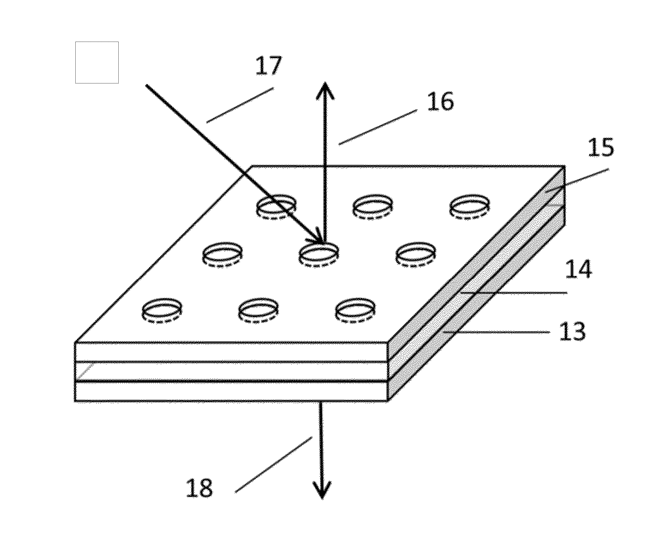
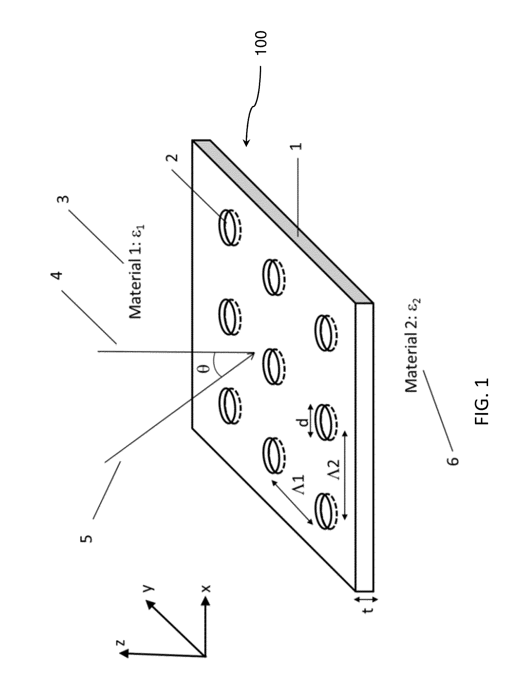
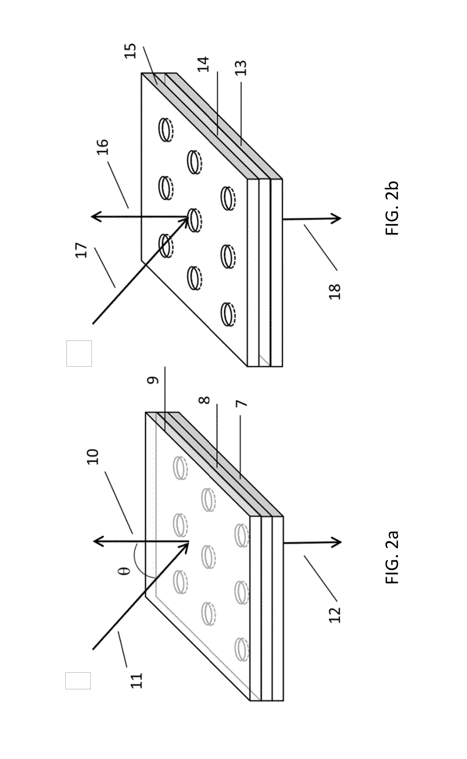
[0020]In conventional lasers, the direction of laser emission is controlled by reflective mirrors which provide optical feedback for light amplification. In contrast, the optical feedback in plasmonic lasers is provided by the intrinsic plasmonic resonance, and the emission direction is controlled by the critical angle of surface plasmonic coupling. In addition, the existence of high losses of metal is a large concern in the development of lasers, especially in the visible wavelength region. The invention described herein makes use of coupling effects among plasmonic modes supported in individual holes to provide an intense feedback for light amplification, leading to the creation of lasers with low threshold, high efficiency, and unidirectional propagation direction.

[0021]The method described in this application also advantageously supplies optical gain media near the metal hole array through a physical approach, and thus is free of the fabrication difficulty inherent in the chemic...


PUM


Abstract

A sub-wavelength scale optical lasing device, for the controlled transfer of a signal in nano- and other small-scale technologies. An array of sub-wavelength size holes is first milled, or otherwise embedded, into a thin metal film. This film is combined with optically active media to compensate for losses of the metal. Optical signals are emitted in the active media, and then transferred to the metal so that surface plasmon polaritons are excited. Lasing occurs as a result of the compensation of plasmonic losses by the available optical gain.

Description

RELATED APPLICATIONS[0001]The present application claims the benefit of U.S. provisional application Ser. No. 61 / 944,129, filed Feb. 25, 2014, the contents of which are hereby incorporated by reference in its entirety.STATEMENT REGARDING GOVERNMENT FUNDING[0002]This invention was made with government support under N00014-13-1-0649 awarded by the United States Office of Naval Research. The government has certain rights in the invention.TECHNICAL FIELD[0003]The present disclosure relates to lasers and specifically to lasers with guided propagation directions.BACKGROUND OF THE INVENTION[0004]Surface plasmons, known as collective electron oscillations, occur at the metal / dielectric interface. Surface plasmons are easily excited either optically or electrically. In current technologies, there are approaches to realize nanolasers by amplifying surface plasmons, provided that optical gain media are introduced in the close vicinity to the metal to compensate for plasmonic losses. In compari...

Claims


Application Information

Patent Timeline
IPC IPC(8): H01S5/10H01S5/323H01S3/08H01S3/16
CPCH01S5/1042H01S3/169H01S3/08H01S5/1046H01S5/323H01S5/041H01S5/1067H01S5/183H01S5/04253
Inventor MENG, XIANGENGLIU, JINGJINGKILDESHEV, ALEXANDER V.SHALAEV, VLADIMIR M.
Owner PURDUE RES FOUND INC
Learn More