Re-deployable mobile above ground shelter

a mobile above-ground shelter and mobile technology, applied in the field of protective shelters, can solve the problems of inability to temporarily relocate people where severe wind events may occur, inability to use expensive subterranean concrete, and inability to temporarily relocate peopl

Active Publication Date: 2015-12-17
RED DOG MOBILE SHELTERS
View PDF24 Cites 5 Cited by
  • Summary
  • Abstract
  • Description
  • Claims
  • Application Information

AI Technical Summary

Benefits of technology

[0009]In one embodiment, a protective shelter including an enclosure having at least a floor, at least one sidewall coupled to the floor, a door, and a roof coupled to the at least one sidewall. The protective shelter further includes one or more members coupled to the enclosure that support the protective shelter on a substrate and a resilient grouser attached to at least one of the one or more members and in contact with the substrate.

Problems solved by technology

If a redeployable or mobile protective shelter is unavailable, personnel that are temporarily located where severe wind events may occur remain at risk.
One of the challenges of providing severe wind event protection for such personnel is the need for the shelter to be able to be easily, quickly and inexpensively relocated to different work sites as the crews frequently relocate.
To resist wind induced overturning, uplift and sliding, some shelters require the use of expensive subterranean concrete footings in addition to the wide width and massive weight of the foundational pads.
Although pre-cast concrete community and industrial shelters are available, their immense weight (approximately 75,000 lbs. or more) requires the use of specially permitted and oversized trucks to haul them and heavy cranes to lift them into place, which renders their temporary redeployment impractical.
In most instances the cost and inconvenience of pouring of a new pad (and the attendant environmental impact of their subsequent demolition and removal) renders impracticable the redeployment of a pad-anchored protective shelter for temporary use.
Although the anchored box shelter design affords a greater degree of shelter mobility than pad-anchored shelter designs, anchored box shelter designs place shelter occupants at high risk of injury as a result of impact induced failure of the exposed anchoring elements.

Method used


Image

  • Re-deployable mobile above ground shelter
  • Re-deployable mobile above ground shelter
  • Re-deployable mobile above ground shelter

Examples


first embodiment

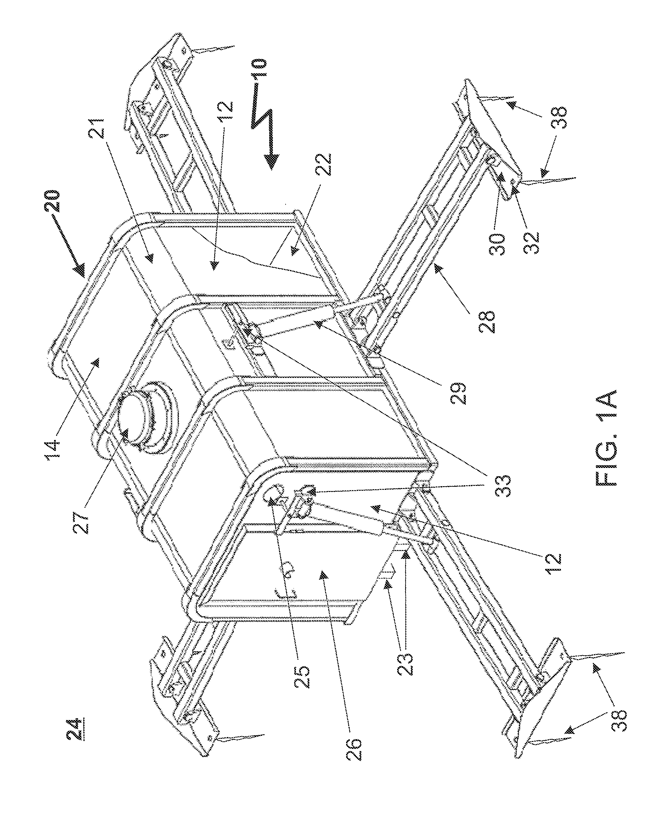
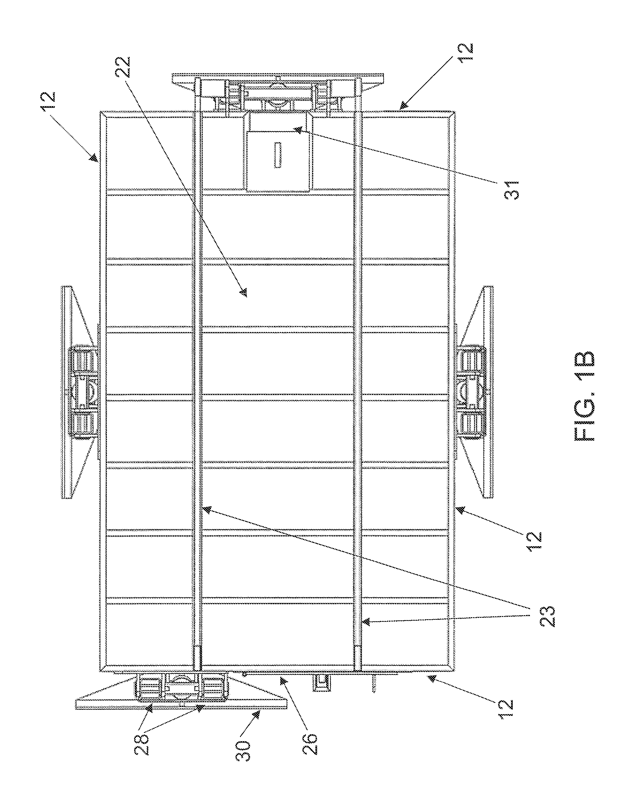
[0035]With reference now to FIG. 1A, there is illustrated a perspective view of the entry end of a protective shelter 10 as seen from above. In an exemplary implementation, protective shelter 10 includes an enclosure 20 constructed of formed and / or welded, reinforced steel (or steel alloy) plate of sufficient strength to protect occupants and contents of protective shelter 10 from high-velocity wind events, impact and penetration by wind borne debris. In the depicted embodiment, enclosure 20 has a generally rectangular prismatic shape having a floor 22, four sidewalls 12, and a roof 14 all formed of reinforced steel plate.

[0036]For example, enclosure 20 can be made of welded A36, ¼″ steel plate with reinforcing ribs of sufficient size, placement and design to meet or exceed deflection and penetration limits established by the National Storm Shelter Association (NSSA) standard, the Federal Emergency Management Agency (FEMA) standards, the American Society of Civil Engineers (ASCE) st...

second embodiment

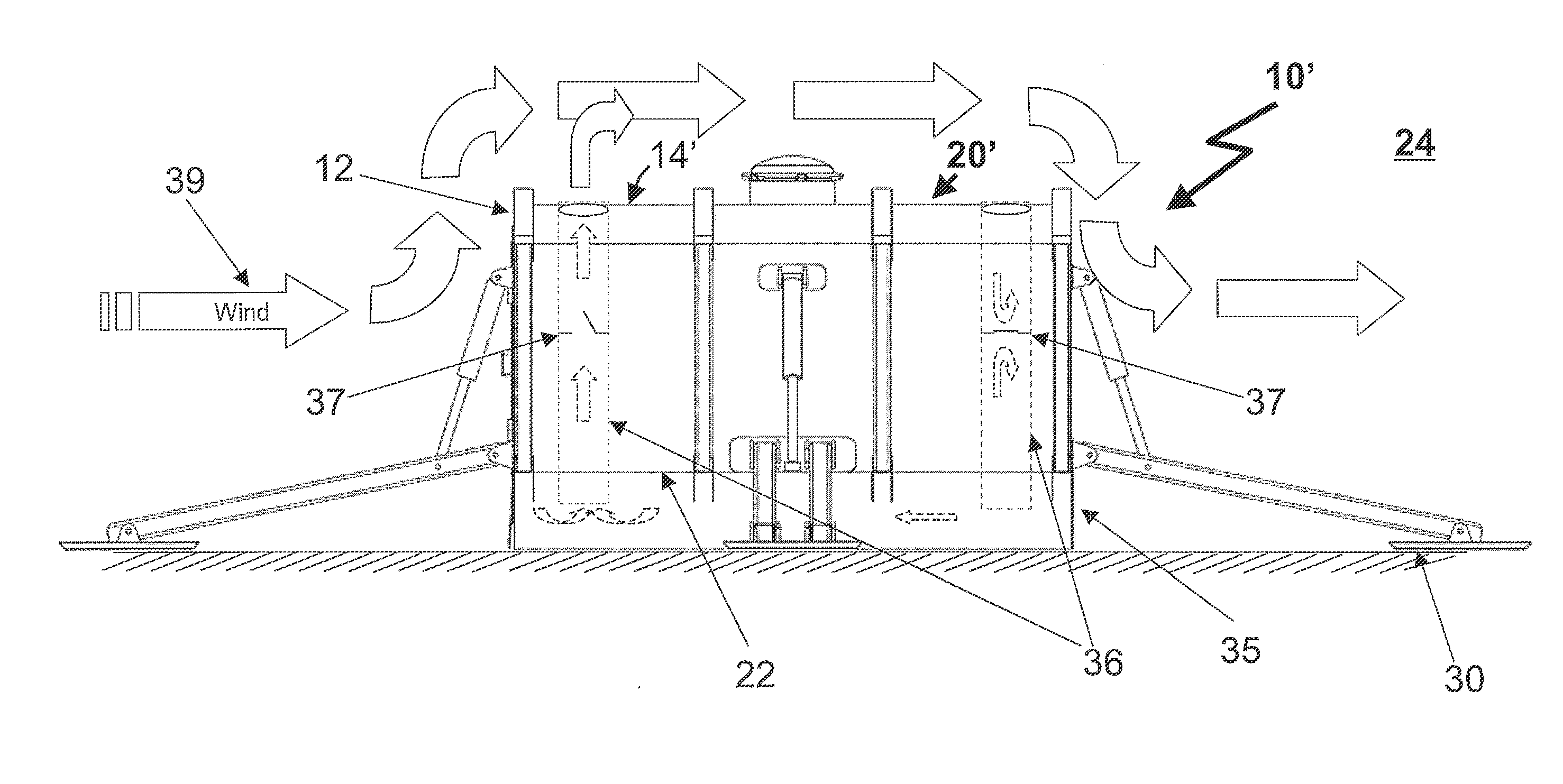
[0046]Referring now to FIGS. 2-3, perspective and elevation views of a protective shelter 10′ are depicted. As indicated by like reference numerals, the construction of protective shelter 10′ is substantially the same as that of protective shelter 10 of FIG. 1. Accordingly, protective shelter 10′ includes an enclosure 20′ including a floor 22, four sidewalls 12 and a roof 14′ all formed of welded plate steel. Protective shelter 10′ may also optionally have stabilizers 28 as previously discussed. Unlike protective shelter 10, protective shelter 10′ further includes rigid skirting 34 surrounding the base of sidewalls 12 to form a lower substantially enclosed sub-floor region (basement air space) below floor 22.

[0047]It will be appreciated that when a solid object of any shape, such as enclosure 20′, is immersed in a flowing stream of fluid (e.g., a wind), areas of relatively lower and higher pressures are created over all the surfaces of that object according to Bernoulli's principle....

third embodiment

[0059]With reference now to FIGS. 7A-7D, there are illustrated top plan, end elevation, perspective and side elevation views, respectively, of the protective shelter 70. As indicated by like reference numerals, protective shelter 70 is constructed similarly to protective shelter 10 of FIGS. 1A-1D, but has an enclosure 80 of greater length to support a higher occupancy rating (e.g., 25 persons versus 12). Because of its greater length, enclosure 80 has a door 26 on each of its longer sidewalls 12 and omits stabilizers 28 on the shorter sidewalls 12.

[0060]Referring now to FIGS. 8A-8B, there are depicted a front end view and left side view of an exemplary protective shelter 70 ready for transport on a roll-off container transport 60. In the depicted embodiment, the roll-off container transport is again a conventional roll-off container trailer, such as model GN-20 or GN-30 available from Domatex Inc. of Houston, Tex. In an alternative embodiment, roll-off container transport 60 can aga...


PUM


Abstract

A protective shelter including an enclosure having at least a floor, at least one sidewall coupled to the floor, a door, and a roof coupled to the at least one sidewall. The protective shelter further includes one or more members coupled to the enclosure that support the protective shelter on a substrate and a resilient grouser attached to at least one of the one or more members and in contact with the substrate.

Description

PRIORITY CLAIM AND CROSS-REFERENCE[0001]The present application is a continuation of U.S. patent application Ser. No. 13 / 917,851, which is incorporated herein by reference in its entirety.BACKGROUND OF THE INVENTION[0002]1. Technical Field[0003]The present invention relates generally to protective shelters, and more particularly to redeployable mobile aboveground shelters.[0004]2. Description of the Related Art[0005]The construction of storm shelters, safe rooms and blast resistant modules is well known and thoroughly documented, for example, in FEMA 320, Third Edition and FEMA 361, Second Edition, both available from the Federal Emergency Management Agency (FEMA), as well as in ICC / NSSA 2008 “Standard for the Design and Construction of Storm Shelters,” published jointly by the International Code Council (ICC) and the National Storm Shelter Association (NSSA) and in Section 6, Wind Loads, of “Minimum Design Loads for Buildings and Other Structures,” SEI / ASCE 7-05, 2005, ISBN: 0-7844...

Claims


Application Information

Patent Timeline
Patent Type & Authority Applications(United States)
IPC IPC(8): E04H9/14E04B1/92E04B1/343
CPCE04H9/14E04B1/34352E04H2001/1283E04B2103/06E04B1/92E04H1/1205Y02B10/30Y02A50/00E04B1/343E04B1/34347E04H1/005E04H9/16
Inventor SCOTT, IV, OSCAR T.
Owner RED DOG MOBILE SHELTERS
Why Eureka
Try Eureka