
Hybrid vehicle control device

a control device and hybrid technology, applied in vehicle position/course/altitude control, process and machine control, instruments, etc., can solve the problems of wasteful depressing of accelerator pedals, unnecessarily starting internal combustion engines, and inability to determine to what extent the accelerator pedal is operated, etc., to suppress the suppress the unnecessary start of internal combustion engines, and suppress the effect of internal combustion engin

Active Publication Date: 2015-12-17
TOYOTA JIDOSHA KK
View PDF6 Cites 4 Cited by
  • Summary
  • Abstract
  • Description
  • Claims
  • Application Information

AI Technical Summary

Benefits of technology

The invention relates to a control device for hybrid vehicles that can prevent the engine from starting unnecessary when the vehicle is started. The control device uses various sensors and parameters to determine when the driver is requesting a smooth start or when they are accidentally pressing the accelerator pedal. By adjusting the starting point of the engine, the control device can prevent the engine from starting when it is not needed, which improves fuel efficiency and reduces emissions. The control device can also adjust the starting point of the engine based on the driver's intent, allowing for a smooth start even when the driver is in a hurry. Overall, the control device helps to improve the performance and experience of hybrid vehicles.

Problems solved by technology

When the vehicle is started from this state, since the internal combustion engine is stopped, the driver cannot determine to what extent the accelerator pedal is operated based on the rotation speed of the internal combustion engine or sound of the internal combustion engine.
For this reason, the internal combustion engine may be unnecessarily started by strongly depressing the accelerator pedal wastefully.

Method used


Image

  • Hybrid vehicle control device
  • Hybrid vehicle control device
  • Hybrid vehicle control device

Examples


first embodiment

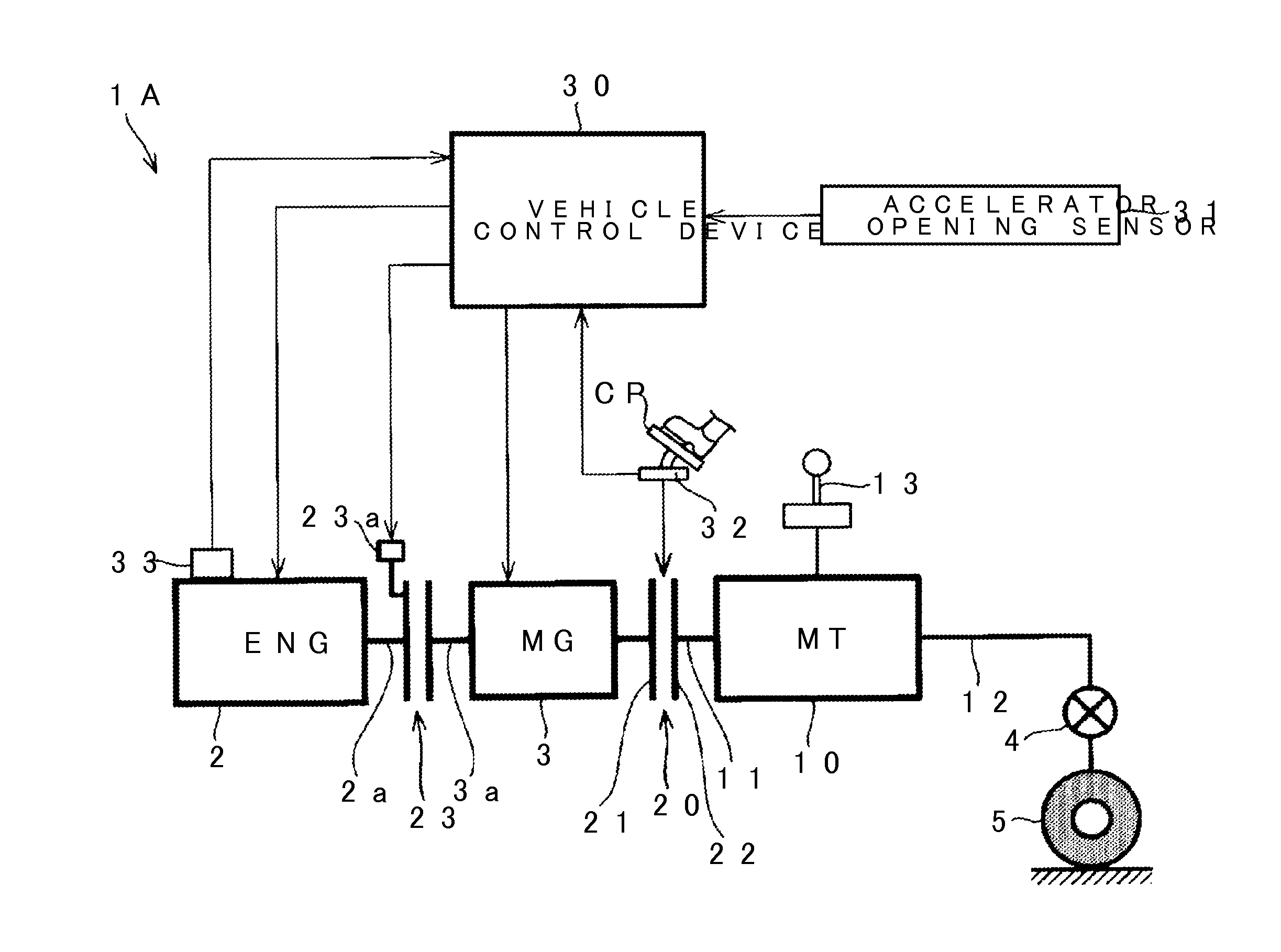
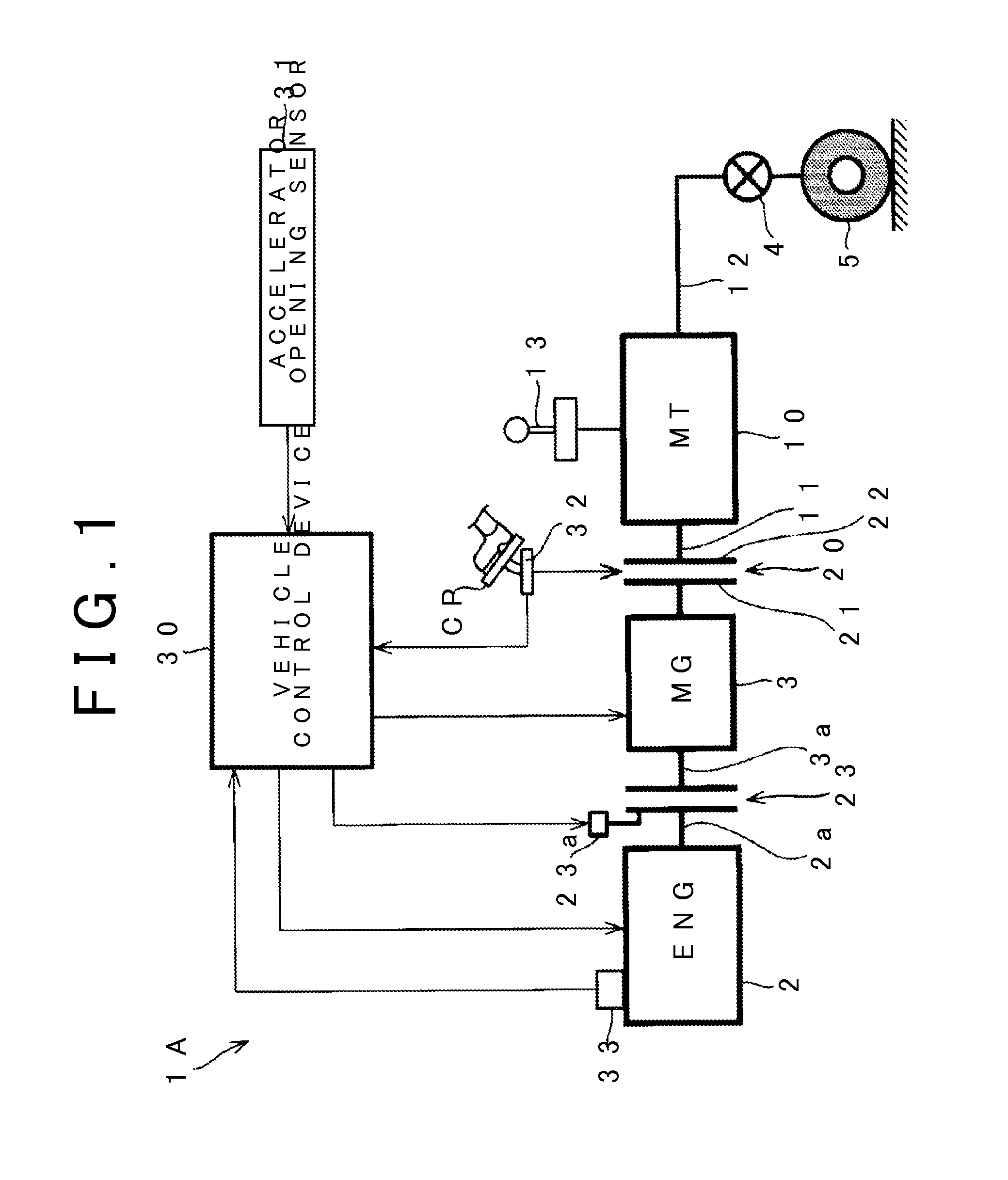
[0025]FIG. 1 schematically shows a main part of a vehicle in which a control device according to a first embodiment of the invention is incorporated. In a vehicle 1A, an internal combustion engine (hereinafter, referred to as an engine) 2 and a motor generator (hereinafter, referred to as MG) 3 as an electric motor are mounted as a drive source for traveling. That is, the vehicle 1A is configured as a hybrid vehicle. The engine 2 is a known spark ignition type internal combustion engine which is mounted in a hybrid vehicle. The MG 3 is a known motor generator which is mounted in a hybrid vehicle and functions as an electric motor and a generator.

[0026]In the vehicle 1A, a manual transmission (hereinafter, abbreviated as a transmission) 10 is mounted. The transmission 10 is configured as a manual transmission having shift gear stages of forward first gear to fifth gear and reverse. The transmission 10 includes an input shaft 11 and an output shaft 12. Gear pairs (not shown) correspon...

second embodiment

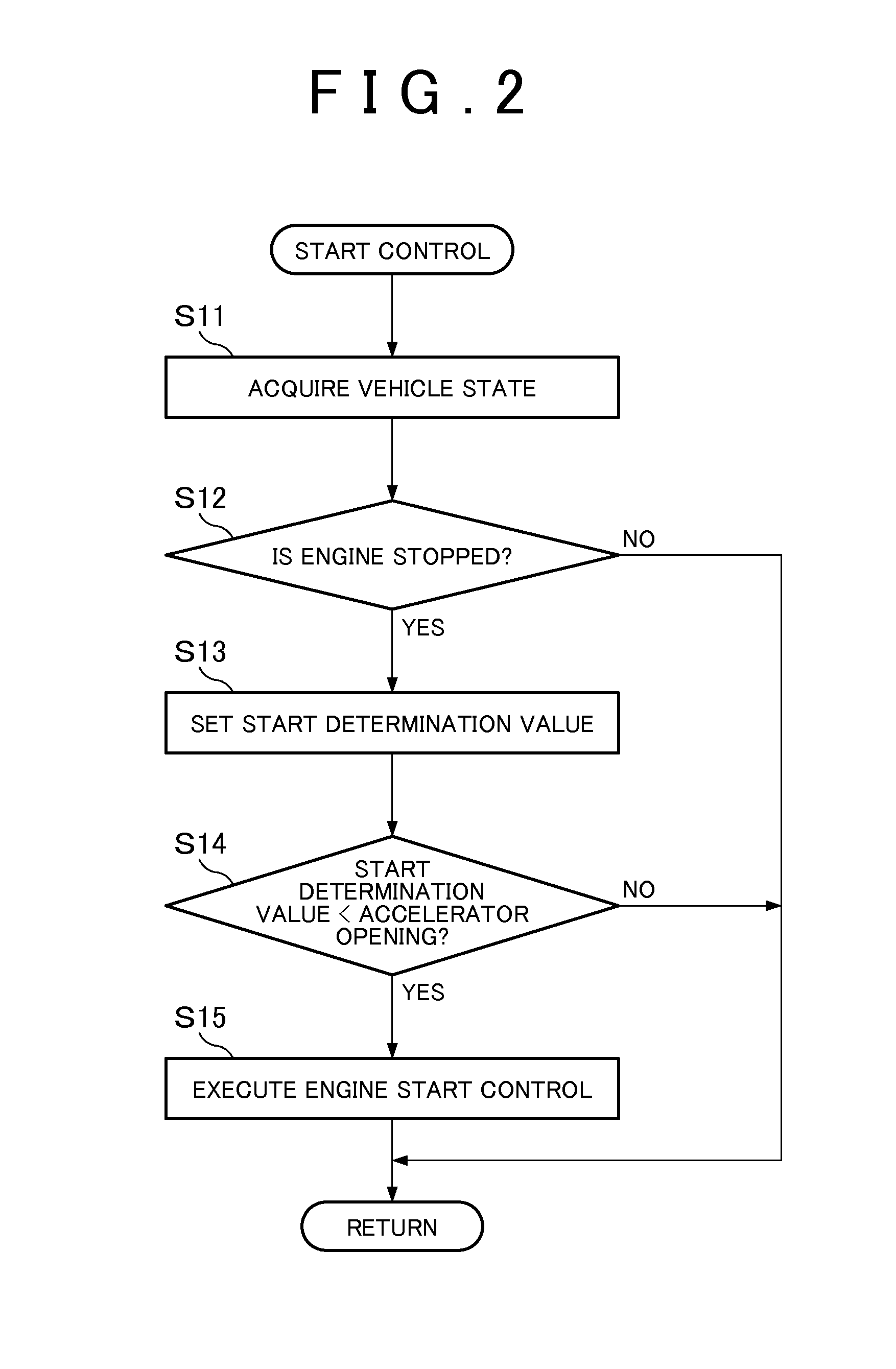
[0040]Next, a control device according to a second embodiment of the invention will be described referring to FIGS. 5 to 7. In this embodiment, FIG. 1 is also referred to with regard to the vehicle 1A. FIG. 5 shows a start control routine which is executed by a vehicle control device 30 in this embodiment. This control routine is repeatedly executed in a predetermined period during stopping of the vehicle 1A. In FIG. 5, the steps common to FIG. 2 are represented by the common reference numerals, and description thereof will not be repeated.

[0041]In the control routine of FIG. 5, the vehicle control device 30 advances processing to Step S12 similarly to the control routine of FIG. 2. In Step S12, when it is determined that the engine 2 is stopped, the process progresses to Step S21, and the vehicle control device 30 determines whether or not the start of the engine 2 is necessary based on the amount of return of the clutch pedal CP and the accelerator opening. FIG. 6 shows a map in w...


PUM


Abstract

A control device is applied to a hybrid vehicle (1A) in which an internal combustion engine (2) and an MG (3) are connected through a second clutch (21), the MG (3) and a transmission (10) are connected through a first clutch (20) whose state is switchable by a depression operation of a clutch pedal (CP), and an output shaft (12) of the transmission (10) is connected to a driving wheel (5) so as to transmit power. The control device starts the internal combustion engine (2) when an accelerator opening is equal to or greater than a start determination value. When the vehicle (1A) is stopped and the internal combustion engine (2) is stopped, and when the amount of return of the clutch pedal (CP) is small, the control device makes the start determination value greater than when the amount of return of the clutch pedal (CP) is great.

Description

TECHNICAL FIELD[0001]The present invention relates to a control device for a hybrid vehicle which is provided with a clutch operable with a clutch pedal in a power transmission path between an internal combustion engine and a driving wheel and is configured to output power from an electric motor to a power transmission path between the clutch and the driving wheel.BACKGROUND ART[0002]A hybrid vehicle in which an internal combustion engine and a motor generator as a drive source for traveling are mounted is known. In this hybrid vehicle, a manual clutch which is operated by a clutch pedal is provided in a power transmission path between the drive source for traveling and a driving wheel. For example, a hybrid vehicle in which a rotation shaft of the motor generator is connected to an output shaft of the internal combustion engine through an automatic clutch, and an input shaft of a manual transmission is connected to the rotation shaft of the motor generator through a manual clutch i...

Claims


Application Information

Patent Timeline
IPC IPC(8): B60W20/00B60W10/06B60W10/02
CPCY10S903/93B60W20/10B60W10/02B60W2710/06B60W2540/14B60W2540/10B60W2710/021B60W10/06B60K6/48B60K6/547B60W20/00B60W30/18027Y02T10/62
Inventor HAYASHIMA, NAOKIMURAKAMI, KOJITANAKA, TAKAAKI
Owner TOYOTA JIDOSHA KK
Learn More