
Feedback receive path with RF filter

a filter and receive path technology, applied in the field of electronic devices, can solve the problems of affecting the effectiveness subject to accuracy degradation, and the application of filters at these frequencies, and reducing the efficiency of the feedback path receiver

Inactive Publication Date: 2015-12-03
QUALCOMM INC
View PDF18 Cites 10 Cited by
  • Summary
  • Abstract
  • Description
  • Claims
  • Application Information

AI Technical Summary

Benefits of technology

The patent text describes a method to reduce the size of transmitters and receivers by using a feedback loop to control transmission power. This method can improve factory calibration time and accuracy degradation due to power supply variation and temperature variation. The text also discusses the use of multiple frequency bands in portable communication devices and the impact of open loop power control on calibration time and accuracy. The technical effects of the patent text include reducing the number of interface pins used in transmitters and receivers, improving factory calibration time, and improving transmission power control accuracy.

Problems solved by technology

Open loop power control can increase factory calibration time, may be subject to accuracy degradation due to power supply variation and temperature variation, and may use a complex look-up table.
Transmit power control methods that detect low-band transmit signals (e.g., at TX 1) using the feedback path receiver may present challenges in a system that simultaneously transmits WLAN transmit signals (e.g., at TX 2) at relatively high power.
That is, these third-order intermodulation signals occur at or near the fundamental frequency TX 1 and fundamental frequency TX 2, and the application of filters at these frequencies would be detrimental to the effectiveness of the feedback path receiver.

Method used


Image

  • Feedback receive path with RF filter
  • Feedback receive path with RF filter
  • Feedback receive path with RF filter

Examples


Embodiment Construction

[0018]The word “exemplary” is used herein to mean “serving as an example, instance, or illustration.” Any aspect described herein as “exemplary” is not necessarily to be construed as preferred or advantageous over other aspects.

[0019]In this description, the term “application” may also include files having executable content, such as: object code, scripts, byte code, markup language files, and patches. In addition, an “application” referred to herein may include files that are not executable in nature, such as documents that may need to be opened or other data files that need to be accessed.

[0020]As used herein, the term “on-line” refers to performing transmit power control such as described herein while a communication device is in use, such as when engaged in a data or voice communication session.

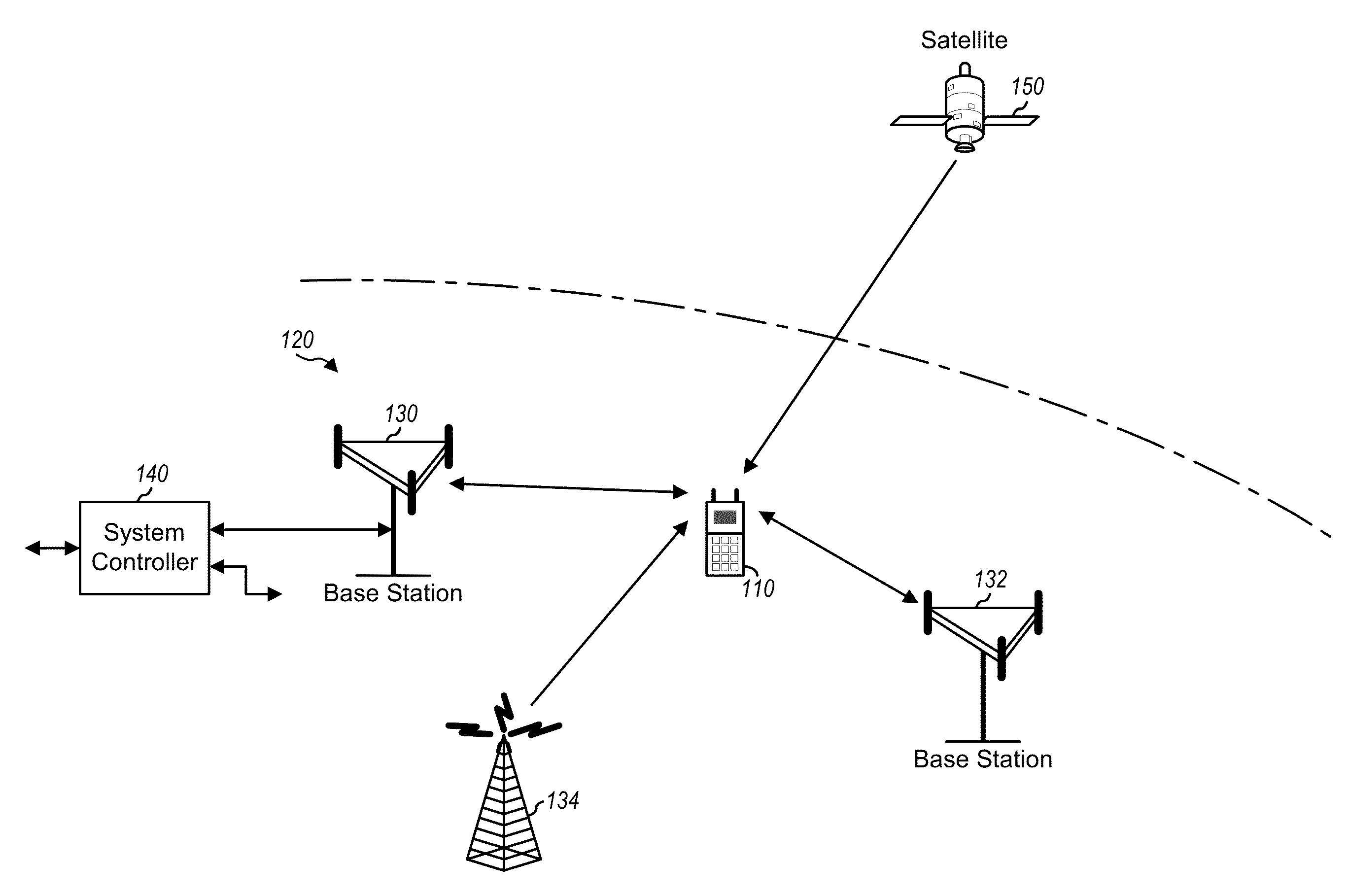
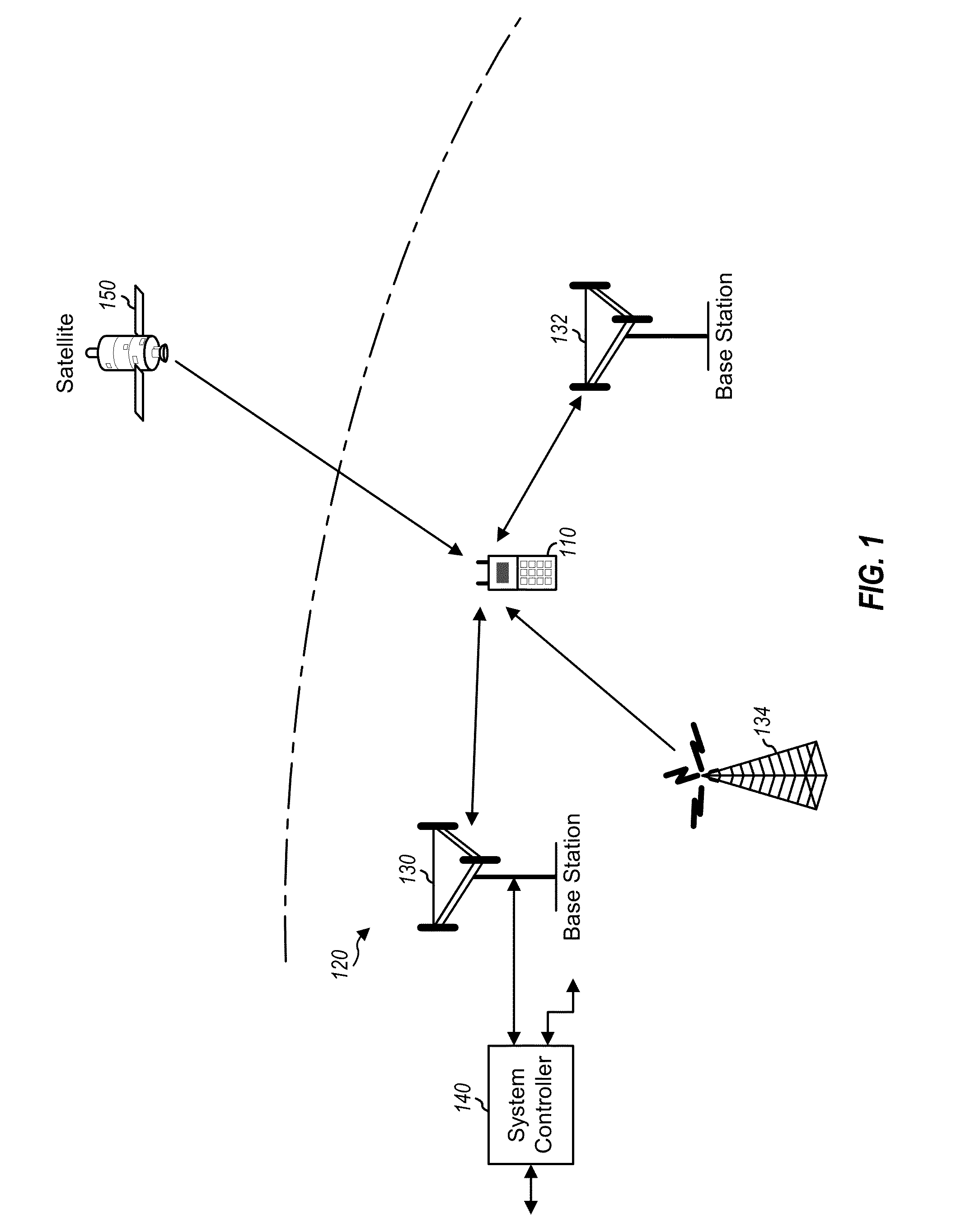
[0021]FIG. 1 is a diagram showing a wireless device 110 communicating with a wireless communication system 120. The wireless communication system 120 may be a Long Term Evolution (LTE) sy...


PUM


Abstract

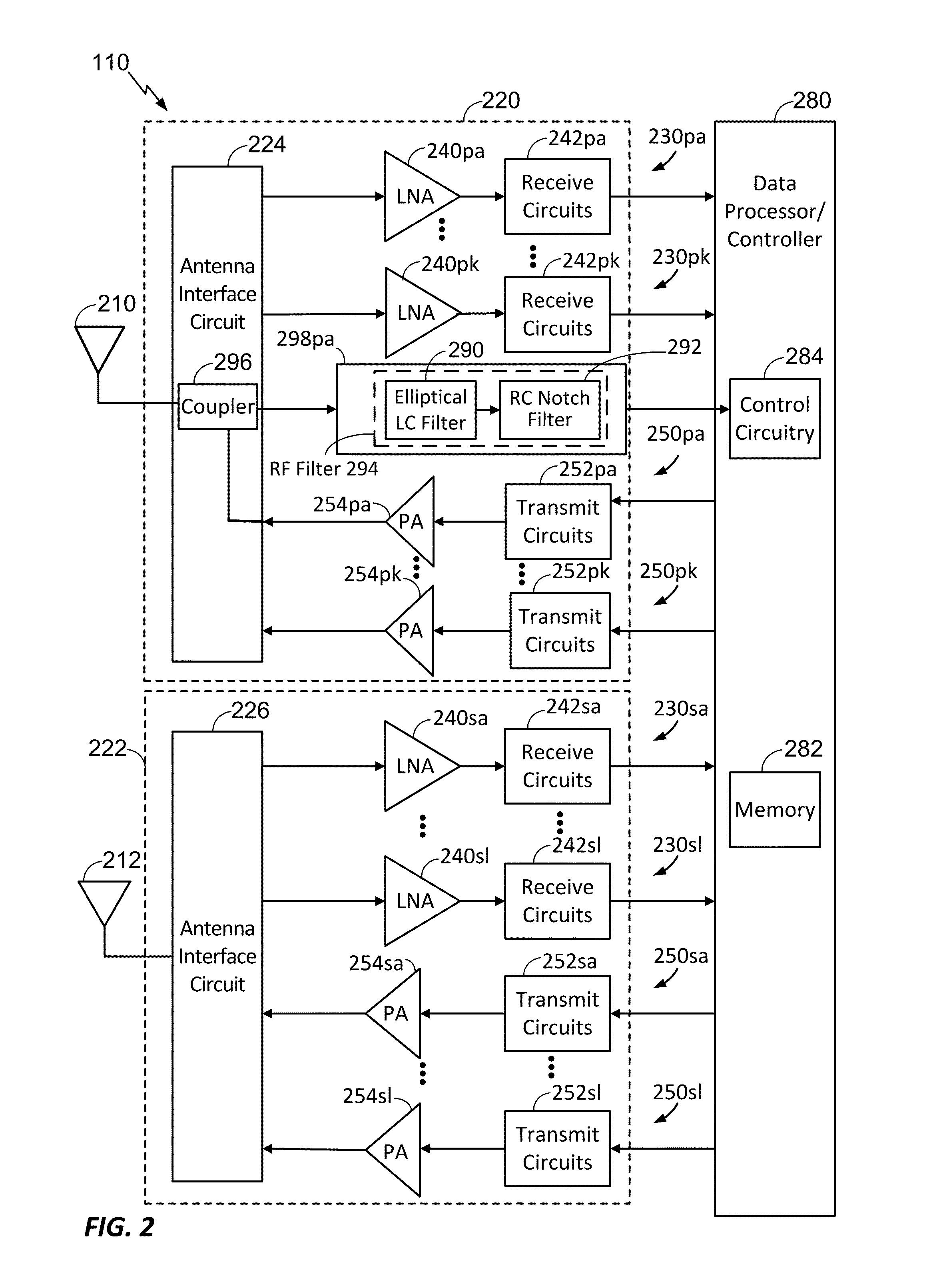
An apparatus includes an elliptical inductance-capacitance (LC) filter and a resistive-capacitive (RC) notch filter serially coupled to the elliptical LC filter. The elliptical LC filter and the RC notch filter are configured to filter a radio-frequency (RF) signal received by a feedback receive path.

Description

I. CROSS-REFERENCE TO RELATED APPLICATIONS[0001]The present application claims priority from U.S. Provisional Patent Application No. 62 / 004,758, filed May 29, 2014 and entitled “RADIO-FREQUENCY MULTIPLE-STAGE FILTER IN A FEEDBACK PATH,” the content of which is incorporated by reference in its entirety.II. FIELD[0002]The present disclosure relates generally to electronics, and more specifically to transmitters and receivers.III. DESCRIPTION OF RELATED ART[0003]It is generally desirable to reduce the die area used for transmitters and receivers. Because die area is sometimes limited by the number of interface pins available, reducing a number of pins may enable die area to be reduced.[0004]Transmit power control may be accomplished using open loop power control. Open loop power control can increase factory calibration time, may be subject to accuracy degradation due to power supply variation and temperature variation, and may use a complex look-up table. Alternatively, a feedback rece...

Claims


Application Information

Patent Timeline
Patent Type & Authority Applications(United States)
IPC IPC(8): H04B1/12H04B15/00
CPCH04B15/00H04B1/12H04B1/0475H04B2001/0416
Inventor RAI, SHAILESH SHEKHARRANJAN, MAHIMGOLDBLATT, JEREMY MARKBOSSU, FREDERICCHELLAPPA, VIJAY
Owner QUALCOMM INC
Learn More