
Input current limited power supply and audio power amplifier for high power reproduction of nondeterministic signals

a technology of input current and limited power supply, applied in power management, high-level techniques, wireless communication, etc., can solve the problems of low-voltage battery, audio fidelity, and audio power

Active Publication Date: 2015-12-03
MOTOROLA SOLUTIONS INC
View PDF0 Cites 18 Cited by
  • Summary
  • Abstract
  • Description
  • Claims
  • Application Information

AI Technical Summary

Benefits of technology

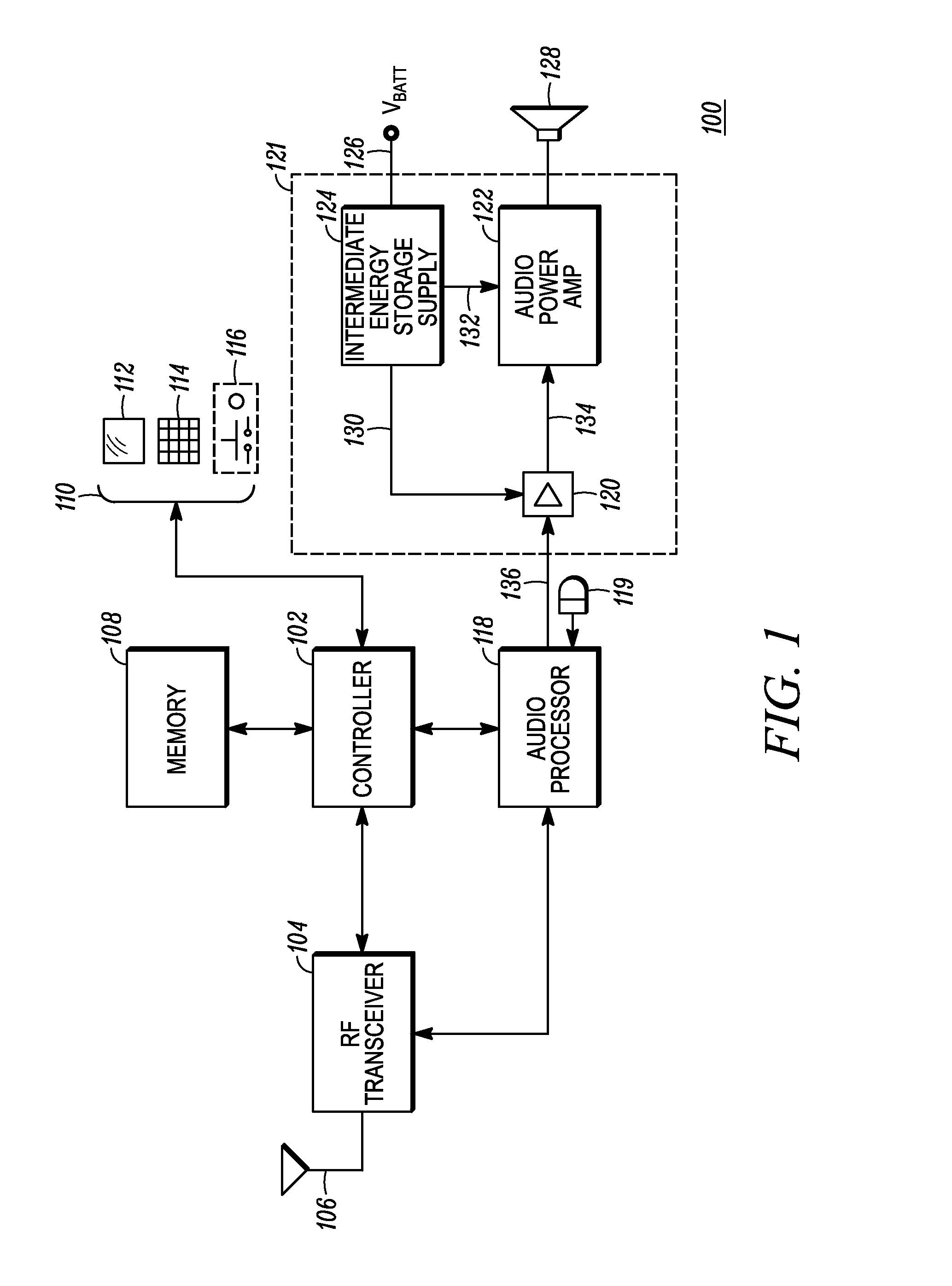
The present invention relates to audio power amplifier circuits for portable two-way radio devices. The technical problem addressed by the invention is the need for sufficient peak audio power to allow the user to hear and understand the received audio in noisy environments, while limiting the current that can be drawn from the battery to avoid exceeding the battery current limit. Conventional audio power amplification methods that rely on the combination of the audio power amplifier supply voltage and the loudspeaker impedance to limit the peak current drawn from the battery result in peak clipping, causing significant distortion and reducing intelligibility. The invention provides a method and apparatus for amplifying received audio signals in a portable two-way radio device under current budgeted conditions in a way that does not exceed the battery current limit and provides sufficient peak audio power to allow the user to hear and understand the received audio in noisy environments.

Problems solved by technology

Given a battery current limit, the use of a lower voltage battery presents a problem with regard to audio fidelity because the power available to the portable two-way radio device is less than that available from a substantially larger battery having a higher nominal voltage under the same battery current limit.
Furthermore, given that the user of the portable two-way radio device can be located in a noisy environment, the audio power needs to be sufficiently loud and distortion-free for the user to understand received audio signals under such conditions.
However, given the limitation on current that can be drawn from the battery under IEC 60950-1, and given the current budget needed to concurrently operate all portions of the portable two-way radio device (e.g. RF transmitter, RF receiver, controller, audio power amplifier etc.) without exceeding the battery current limit, and in view of the losses due to inefficiency, it is not possible to draw the necessary instantaneous current directly from the battery to support instantaneous 12 W peak audio power.
As a result, using conventional audio power amplification that relies on the combination of audio power amplifier supply voltage, or maximum peak output voltage of the audio power amplifier, and loudspeaker impedance to limit the peak current drawn from the battery to the budgeted value, peak clipping will occur, causing significant distortion and reducing intelligibility.
When large signals with low crest factor are being amplified, however, or when the speech signals simply require more average power (at a given volume setting) than can be provided, the energy storage in the intermediate energy storage circuit 124 can be depleted, causing the source voltage 132 to drop low enough to otherwise result in peak clipping at the audio power amplifier 122.
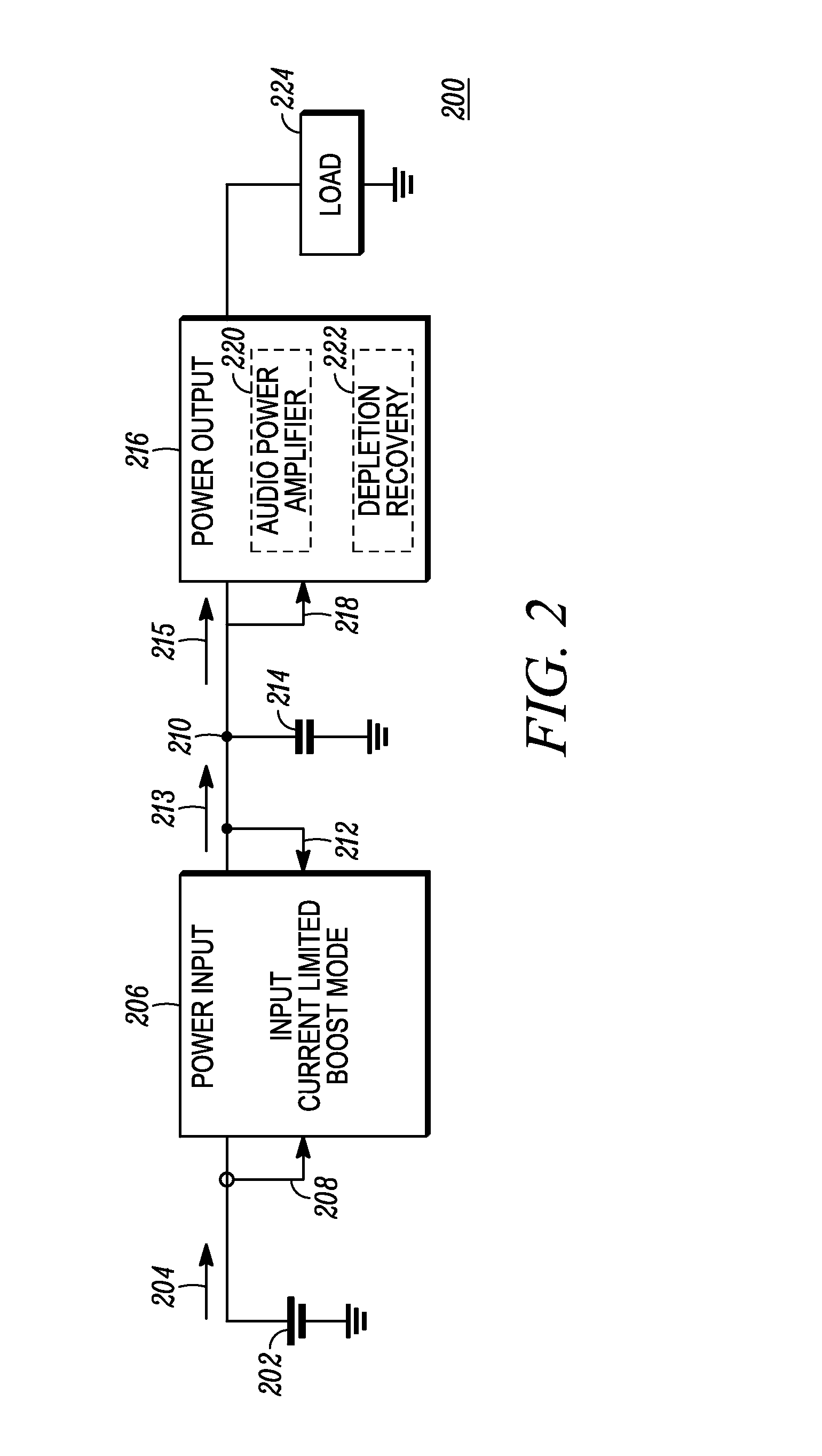
However, if the average power consumed by the power output stage 216 for one or more pitch periods exceeds that which can be provided by the power input stage 206, the voltage on line 210 will continue to decrease and may eventually reach a critically low level, causing a depletion state.
Obviously, for a given required amount of stored energy a higher nominal boost voltage results in the boost capacitor being smaller in capacitance and physical size.
Assuming that the duty cycle of peak power in the pitch period is independent of pitch period, the most difficult signal to work with is that with maximum pitch period (i.e. a deep male voice).

Method used


Image

  • Input current limited power supply and audio power amplifier for high power reproduction of nondeterministic signals
  • Input current limited power supply and audio power amplifier for high power reproduction of nondeterministic signals
  • Input current limited power supply and audio power amplifier for high power reproduction of nondeterministic signals

Examples


Embodiment Construction

[0015]Some embodiments as disclosed herein include a method for powering an audio power amplifier includes boosting a voltage level of a battery to a boost voltage level across a boost capacitor at an output of a boost stage without exceeding a preselected input current limit. The boost voltage level is higher than the voltage level of the battery and higher than a supply voltage required for the audio power amplifier to output a predefined maximum peak power into a load. The method further includes deriving the supply voltage from the boost voltage and providing the supply voltage to the audio power amplifier to power the audio power amplifier. The audio power amplifier amplifies an input signal to produce an amplified signal. The method further includes comparing a state of charge indication parameter to a depletion threshold, wherein the state of charge indication parameter is dependent on the boost voltage, and, when the state of charge indication parameter is below the depletio...


PUM


Abstract

A method and apparatus for amplifying audio signals without exceeding an input current limit budgeted for the audio power amplifier circuit includes an intermediate energy storage between a battery and the audio power amplifier which provides an energy reserve to support amplifying peaks where the peaks have a peak power that is greater than the power that can be drawn from the battery due to the input current limit. Speech signals, which include substantial periodic content having short peaks relative to a pitch period, can be amplified without depleting the intermediate energy storage, allowing the intermediate energy storage to recover after a peak and before occurrence of a next peak. When an audio signal is amplified that results in depletion of the intermediate energy storage, a depletion recovery circuit reduces the overall audio gain to reduce the power demand of the audio power amplifier so as to substantially avoid distortion.

Description

FIELD OF THE DISCLOSURE[0001]The present disclosure relates generally to audio power amplifier circuits, and more particularly to audio power amplifiers for battery powered portable devices where current sourced by the battery is limited and the signal being amplified may require more instantaneous power than can be sourced from the battery due to the current limit.BACKGROUND[0002]The International Electrotechnical Commission, in standard IEC 60950-1, limits the current that can be drawn from a battery having less than 30 volts open circuit voltage to 8 amperes for battery powered devices. Accordingly, this standard applies to virtually all portable two-way radio devices, many of which operate at either a 3.6 volts or a 7.2 volts nominal operating voltage. These nominal voltage levels are achieved using one equivalent lithium ion battery cell for the 3.6 V nominal output voltage, or the equivalent of two lithium ion cells connected in series to achieve the 7.2 V nominal output. Sinc...

Claims


Application Information

Patent Timeline
IPC IPC(8): H03G3/00H04W52/02H03F3/181
CPCH03G3/004H03F2200/03H04W52/0261H03F3/181H03F3/187H03F1/0227H03F2200/321H03G3/007Y02D30/70H03F1/30H03F1/52H03G11/00
Inventor SVENDSEN, PETER WILLIAM HILDING
Owner MOTOROLA SOLUTIONS INC
Learn More