
White light emitting device comprising a plurality of light emitting diodes with different peak emission wavelengths and a wavelength converter

a light emitting device and wavelength converter technology, applied in the field of light emitting devices, can solve the problems of inability to provide high white emission properties, exhibited non-uniform color, color irregularity, etc., and achieve the effect of reducing the number of light emitting diodes

Active Publication Date: 2011-12-06
SEOUL SEMICONDUCTOR
View PDF215 Cites 245 Cited by
  • Summary
  • Abstract
  • Description
  • Claims
  • Application Information

AI Technical Summary

Benefits of technology

The present invention provides an LED that has a high color temperature and a high color rendering index, making it suitable for various applications such as electronic products, home appliances, audio systems, and communication products. The LED comprises one or more light emitting diodes that emit different wavelengths of light, and a wavelength-conversion means that converts the primary light into secondary light in a visible light wavelength range. The LED has a high color temperature of about 2000 to 80000 K and a high color rendering index of 90 or more. The LED can be used for lighting fixtures and various exterior and interior displays, including automobiles. The LED chip package or top package can be formed into a lamp package or a high output package for increased heat emission efficiency.

Problems solved by technology

In particular, non-uniform color, such as color irregularity, is exhibited.
However, the above second method is disadvantageous because it cannot provide high white emission properties due to the YAG phosphor.
Therefore, limitations are imposed on applications of the conventional white LEDs to various products.
In particular, such an LED cannot be used for lighting fixtures.

Method used


Image

  • White light emitting device comprising a plurality of light emitting diodes with different peak emission wavelengths and a wavelength converter
  • White light emitting device comprising a plurality of light emitting diodes with different peak emission wavelengths and a wavelength converter
  • White light emitting device comprising a plurality of light emitting diodes with different peak emission wavelengths and a wavelength converter

Examples


first embodiment

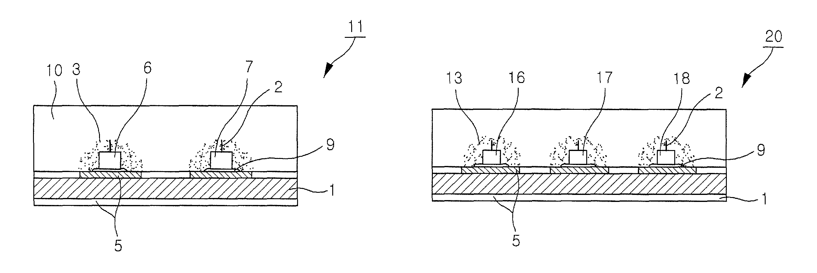
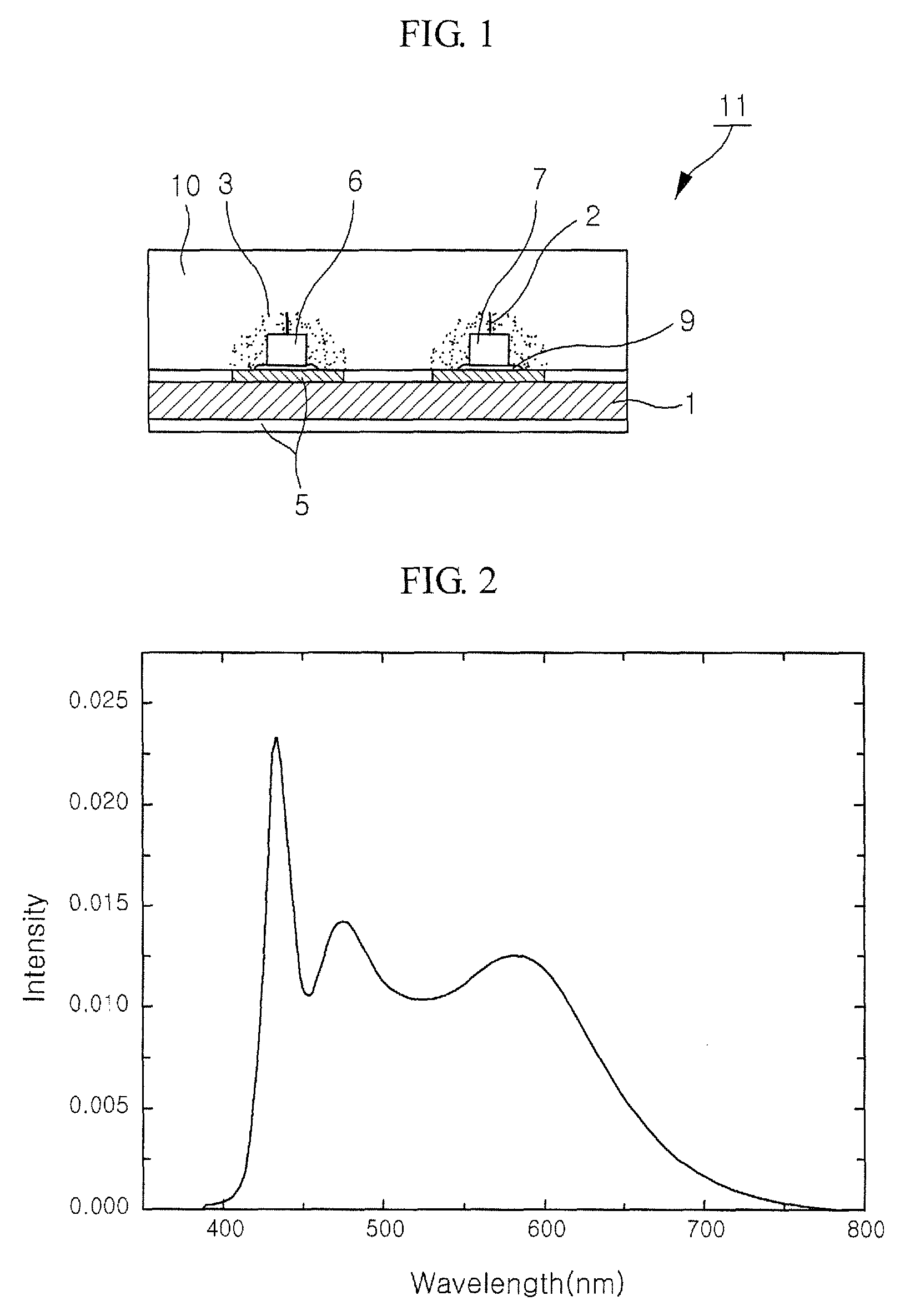
FIG. 1 is a longitudinal sectional view schematically showing an LED according to the present invention, in which a chip package including two light emitting diodes and a wavelength-conversion means is shown. As shown in the drawing, a substrate 1 has electrode patterns 5 formed on both surfaces thereof, and two light emitting diodes 6 and 7 to primarily generate blue light having different wavelengths are mounted on either electrode pattern 5. The light emitting diodes 6 and 7 are mounted on the electrode pattern 5 using a conductive adhesive 9, and electrodes of the light emitting diodes 6 and 7 are connected to another electrode pattern (not shown) by means of a conductive wire 2.

A wavelength-conversion means 3 is placed on upper surfaces and side surfaces of the two light emitting diodes 6 and 7. The wavelength-conversion means 3 functions to convert blue light generated by the light emitting diodes 6 and 7 into secondary light in the visible light wavelength range. The waveleng...

second embodiment

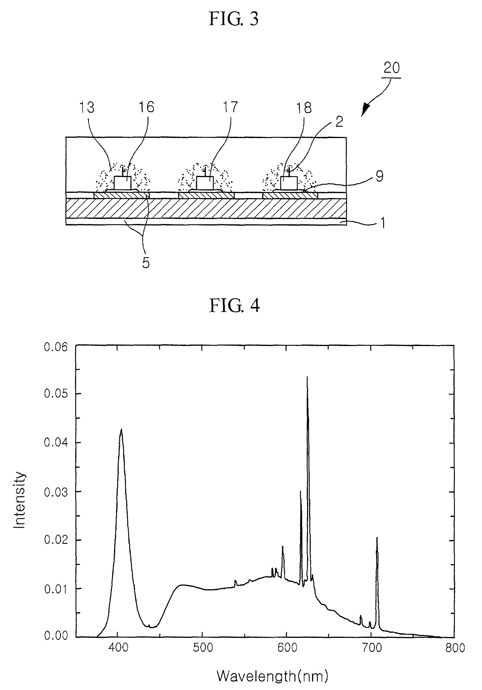
FIG. 5 shows the emission spectrum of the chip package including the three light emitting diodes 16, 17 and 18 having different peak emission wavelengths and the wavelength-conversion means 13 composed of the phosphors having peak emission wavelengths corresponding to green and orange light, according to the The chip package has a color temperature of about 6800 K and a color rendering index of 93.

The technical characteristics of the present invention, concerning FIGS. 1 to 5, are not limited only to the chip package, and may be applied to various LED packages, thus achieving the same objects and effects.

Hereinafter, the embodiments in which the present techniques are applied to various LED packages are described, with reference to the appended drawings, in which the same reference numerals are used throughout the different drawings to designate the same components and structures in FIGS. 1 to 5 and the technical principles relating to the light emitting diode and the wavelength-co...

fifth embodiment

FIG. 8 is a longitudinal sectional view showing a lamp package according to the present invention. The lamp package 50 includes a pair of lead electrodes 51 and 52. A diode holder 53 is formed at an upper end of the lead electrode 51. The diode holder 53 is cup-shaped, in which two light emitting diodes 6 and 7 or three light emitting diodes 16, 17 and 18 are mounted. The light emitting diodes 6 and 7 or 16, 17 and 18 have different peak emission wavelengths, as in the above embodiments. The electrodes of the light emitting diodes 6 and 7 or 16, 17 and 18 are connected to the other lead electrode 52 by means of the conductive wire 2.

The inner wall of the cup-shaped holder 53 is coated with an epoxy resin 54 mixed with a predetermined amount of wavelength-conversion means 3 or 13. The wavelength-conversion means 3 includes a plurality of phosphors having different peak emission wavelengths, which are mixed with each other at an appropriate ratio, as in the above embodiments. Further,...


PUM


Abstract

Disclosed herein is a light emitting device including one or more light emitting diodes to primarily emit light having different wavelengths in the wavelength range of ultraviolet rays and / or blue light, and a wavelength-conversion means to convert the primary light into secondary light in the visible light wavelength range. The light emitting device of the current invention has a high color temperature of 2000 to 8000 K or 10000 K and a high color rendering index of 90 or more, thus easily realizing desired emission on the color coordinate system. Therefore, the lighting emitting device is applicable to mobile phones, notebook computers, and keypads or backlight units for various electronic products, and, in particular, automobiles and exterior and interior lighting fixtures.

Description

TECHNICAL FIELDThe present invention relates, in general, to a light emitting device (LED), and more particularly, to an LED comprising at least one light emitting source and a wavelength-conversion means to convert a wavelength of light generated by the light emitting source into a wavelength exhibiting a predetermined color of light.BACKGROUND ARTGenerally, an LED is advantageous because it has low power consumption and a long lifetime, and also, it can be mounted in limited spaces and is highly resistant to vibration. Recently, single color LEDs, for example, red, blue or green LEDs, and as well, white LEDs have been disclosed. Of these LEDs, the white LED is expected to be increasingly used as it is applied to automotive products and lighting fixtures.In the LED techniques, white color is mainly realized by the two following methods. In the first method, red, blue and green light emitting diodes are disposed to be adjacent to one another, and colors of light emitted by the light...

Claims


Application Information

Patent Timeline
Patent Type & Authority Patents(United States)
IPC IPC(8): H01L29/18H01L25/075H01L33/50
CPCH01L25/0753H01L33/486H01L33/50H01L33/60H01L2224/48091H01L2224/48247H01L2224/73265H01L2924/00014H01L2224/32013H01L2224/8592A63C19/065A63C2019/067
Inventor LEE, CHUNG-HOONROTH, GUNDULATEWS, WALTER
Owner SEOUL SEMICONDUCTOR
Learn More