Method of manufacturing fluorescent lamp and fluorescent lamp manufactured using the same

a technology of fluorescent lamps and manufacturing methods, which is applied in the manufacture of electric discharge tubes/lamps, cold cathode manufacturing, and electrical discharge tubes/lamps, etc., can solve the problems of inability to precisely position filaments, blockage of exhaust tubes, and lead-in wire b>13/b> breaking, so as to reduce the length of glass tubes, reduce the luminous efficiency, and reduce the length

Inactive Publication Date: 2015-12-03
KANG SEONG JIN
View PDF0 Cites 1 Cited by
  • Summary
  • Abstract
  • Description
  • Claims
  • Application Information

AI Technical Summary

Benefits of technology

The present invention provides a full spiral type lamp that solves a problem where a straight portion of a predetermined length should be maintained due to the height of a flare inserted into a glass tube. The stem is located outside the discharge glass tube to relatively reduce the length of the glass tube while having the same luminous efficiency and using a smaller amount of fluorescent substance. The method of manufacturing the fluorescent lamp also eliminates problems where the exhaust tube is blocked or the lead-in wire is cut during the sealing process, reducing the manufacturing cost and the use of pollutants. The stem is located outside the discharge glass tube, thus eliminating the space occupied by the flare and reducing the manufacturing cost. The pinch sealing process is performed on the middle portion of the flare, preventing the exhaust tube from being blocked and avoiding the necessity of performing the additional process of clearing the exhaust tube and reducing the number of defective products resulting from the lead-in wire.

Problems solved by technology

However, due to heat caused by this process, frequently, the exhaust tube 15 may be blocked or the lead-in wire 13 may be broken.
For this reason, when the stem is coupled to a curved track of a spiral type lamp that has a rapid increase in demand in recent years, it is almost impossible to precisely position the filament on a central portion of the discharge glass tube, so that it is impossible to implement a substantially full spiral type lamp.
In such a half spiral type lamp, an additional process, such as a process of bending the glass tube, is required, and it is difficult to realize automation due to positional precision.
In case of bending the lead-in wire at a predetermined angle, a process of positioning the filament on the central portion of the glass tube is required, thus making it difficult to automate the lamp manufacturing process, in addition to deteriorating work efficiency because of a manual operation.
Particularly, defective products may frequently occur, in which the filament is in contact a wall of the glass tube, thus incurring serious problems.

Method used


Image

  • Method of manufacturing fluorescent lamp and fluorescent lamp manufactured using the same
  • Method of manufacturing fluorescent lamp and fluorescent lamp manufactured using the same
  • Method of manufacturing fluorescent lamp and fluorescent lamp manufactured using the same

Examples


Embodiment Construction

[0035]The present invention provides a method of manufacturing a fluorescent lamp and a fluorescent lamp manufactured using the same, which proposes a stem of a novel structure, thus being applicable to a general straight type fluorescent lamp and especially a spiral type fluorescent lamp, and thereby implementing a full spiral type fluorescent lamp while simultaneously simplifying and automating a manufacturing process, in addition to reducing the number of defective products.

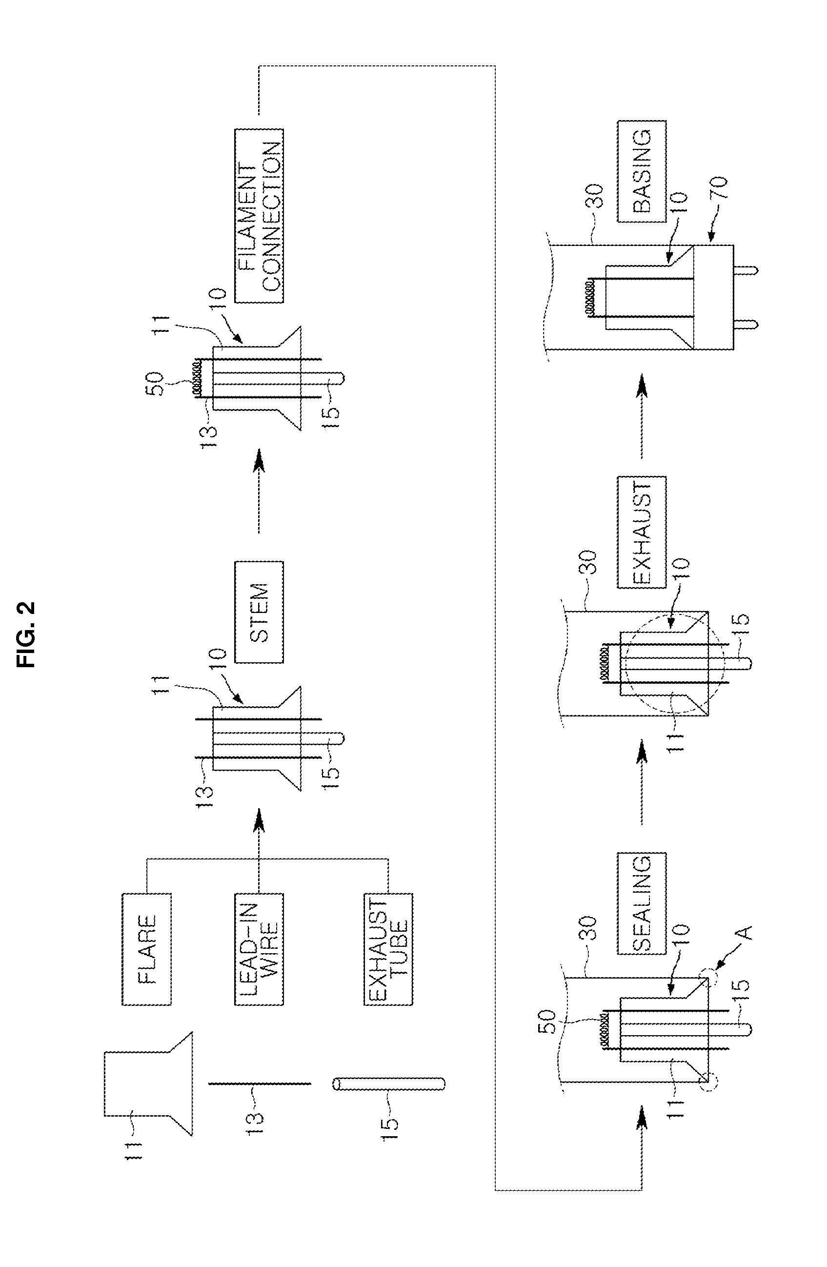
[0036]FIG. 3 is a flow diagram showing a process of manufacturing a fluorescent lamp according to an embodiment of the present invention. The method of manufacturing the fluorescent lamp according to the present invention will be described with reference to FIG. 3.

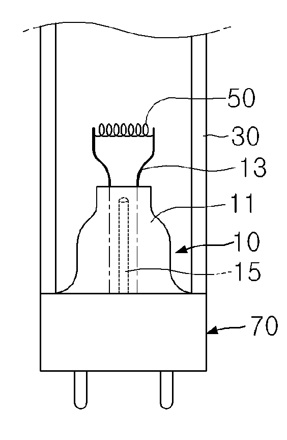
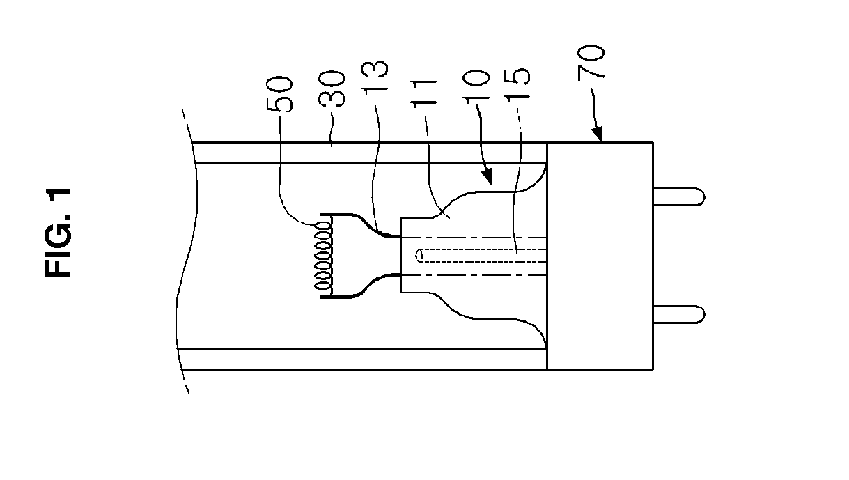
[0037]First, a flare 110, a lead-in wire 130 and an exhaust tube 150 are prepared. In this respect, preferably, the flare 110 is formed such that its upper surface corresponds to a cross-sectional area of an end of a discharge glass tube that is to b...


PUM


Abstract

Disclosed herein are a method of manufacturing a fluorescent lamp and a fluorescent lamp manufactured using the same. The method includes preparing a flare having an upper surface that corresponds to a cross-sectional area of a glass tube of the lamp, manufacturing a stem by forming a lead-in wire and an exhaust tube that pass from a lower surface of the flare to the upper surface thereof and connecting a filament to the lead-in wire of the stem, and melting a circumference of the upper surface of the flare of the stem, introducing the filament into the glass tube via an opening thereof, and contact sealing the upper surface of the flare to an end of the glass tube in such a way that the stem is located outside the glass tube.

Description

REFERENCE TO RELATED APPLICATIONS[0001]This application is a U.S. National Phase application of International Application No. PCT / KR2013 / 002324, filed on Mar. 21, 2013, which designates the United States and claims priority of Korean Patent Application No. 10-2012-0028665, filed on Mar. 21, 2012, the entire contents of which are incorporated herein by reference.FIELD OF THE INVENTION[0002]The present invention relates, in general, to a method of manufacturing a fluorescent lamp and a fluorescent lamp manufactured using the same and, more particularly, to a method of manufacturing a fluorescent lamp and a fluorescent lamp manufactured using the same, which proposes a novel structure for a stem supporting a filament in the fluorescent lamp, thus achieving the easy formation of a general fluorescent lamp as well as a full spiral type fluorescent lamp or a short leg half spiral type fluorescent lamp that is 8 mm or less in its straight portion for receiving the filament.BACKGROUND OF TH...

Claims


Application Information

Patent Timeline
Patent Type & Authority Applications(United States)
IPC IPC(8): H01J9/32H01J9/395H01J9/385H01J19/58H01J19/62
CPCH01J9/326H01J19/58H01J9/395H01J9/385H01J19/62H01J9/247H01J61/0672H01J61/322H01J61/361H01J9/24H01J9/40H01J61/36
Inventor KANG, SEONG JINKANG, SEONG SEOK
Owner KANG SEONG JIN
Why Eureka
Try Eureka