
Gas turbines in mechanical drive applications and operating methods

a technology of gas turbines and mechanical drives, applied in mechanical equipment, machines/engines, electric generator control, etc., can solve the problems of large footprint, complex system b>101/b>, and fluctuation of power availability

Active Publication Date: 2015-12-03
NUOVO PIGNONE SPA
View PDF9 Cites 111 Cited by
  • Summary
  • Abstract
  • Description
  • Claims
  • Application Information

AI Technical Summary

Benefits of technology

The patent describes a system that combines a gas turbine with a reversible electric machine to create a hybrid system. The electric machine can act as a motor or generator to provide additional power to the system. The gas turbine produces mechanical power from the combustion of fuel and air, which is then converted into electrical power by the electric machine and sent to the grid. This system can be used to drive a load without the need for a separate starter. The gas turbine and electric machine are mechanically connected, allowing for the transfer of power between them. The system also includes a flow-conditioning arrangement to modify the air or combustion gas flow through the gas turbine. The technical effects of this patent are improved efficiency and flexibility of the gas turbine system, as well as reduced emissions and noise.

Problems solved by technology

Natural gas is often liquefied for storage or transportation purposes, e.g. if pipeline transportation is not possible or economically unfeasible.
This causes power availability fluctuations both in the 24 hours as well as during the year, due to daily and seasonal temperature fluctuations.
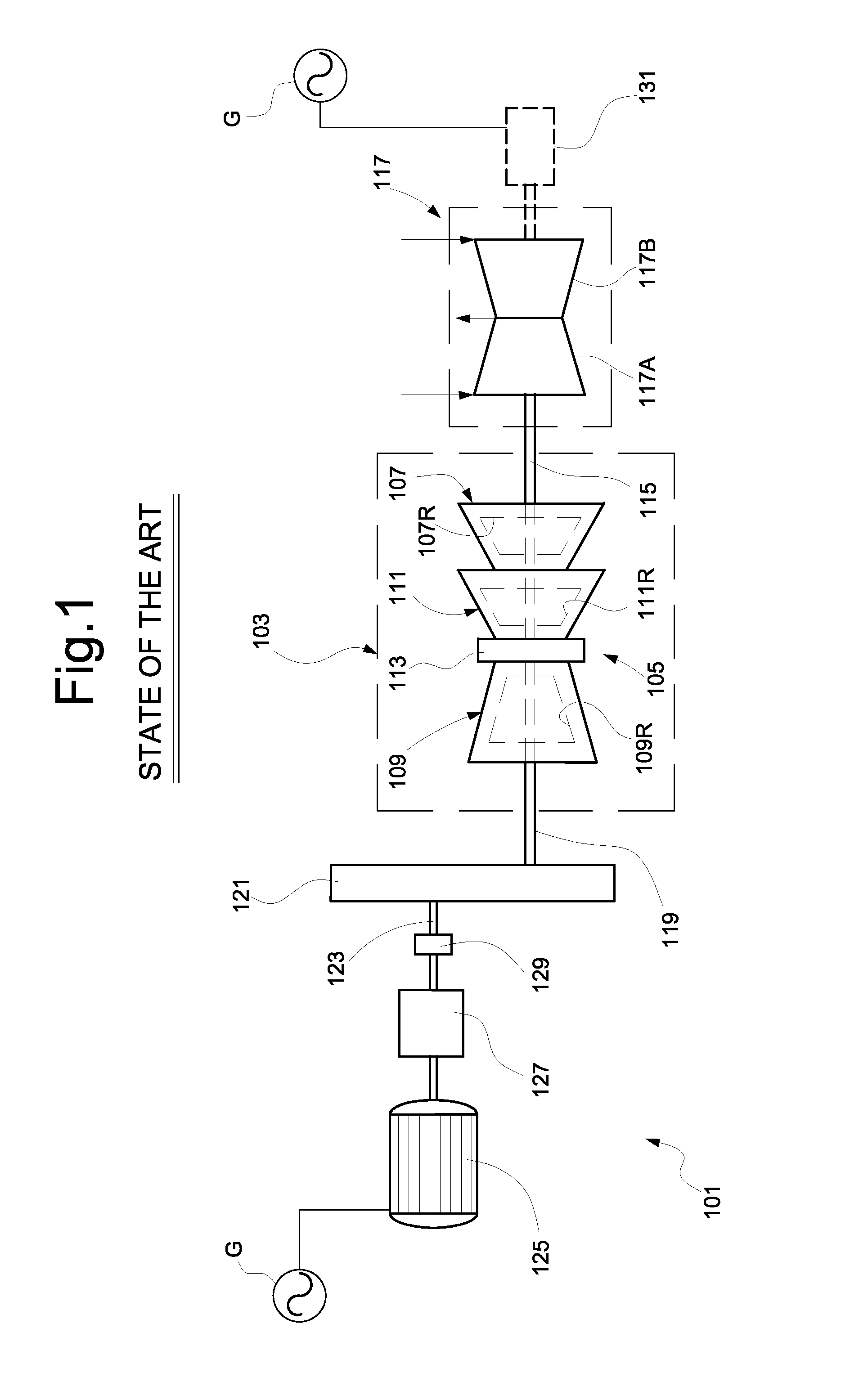
The system 101 is complex and has a large footprint.

Method used


Image

  • Gas turbines in mechanical drive applications and operating methods
  • Gas turbines in mechanical drive applications and operating methods
  • Gas turbines in mechanical drive applications and operating methods

Examples


Embodiment Construction

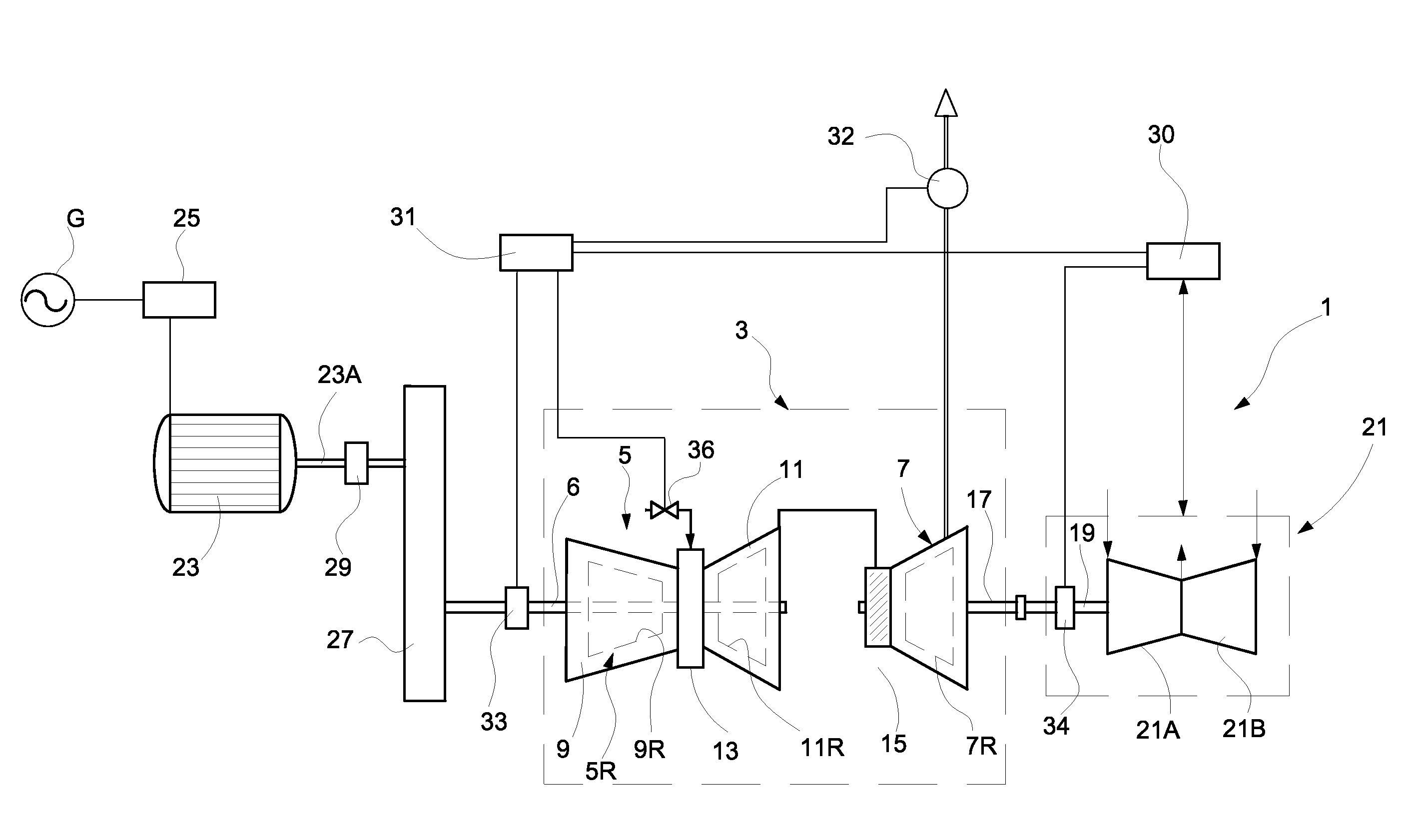
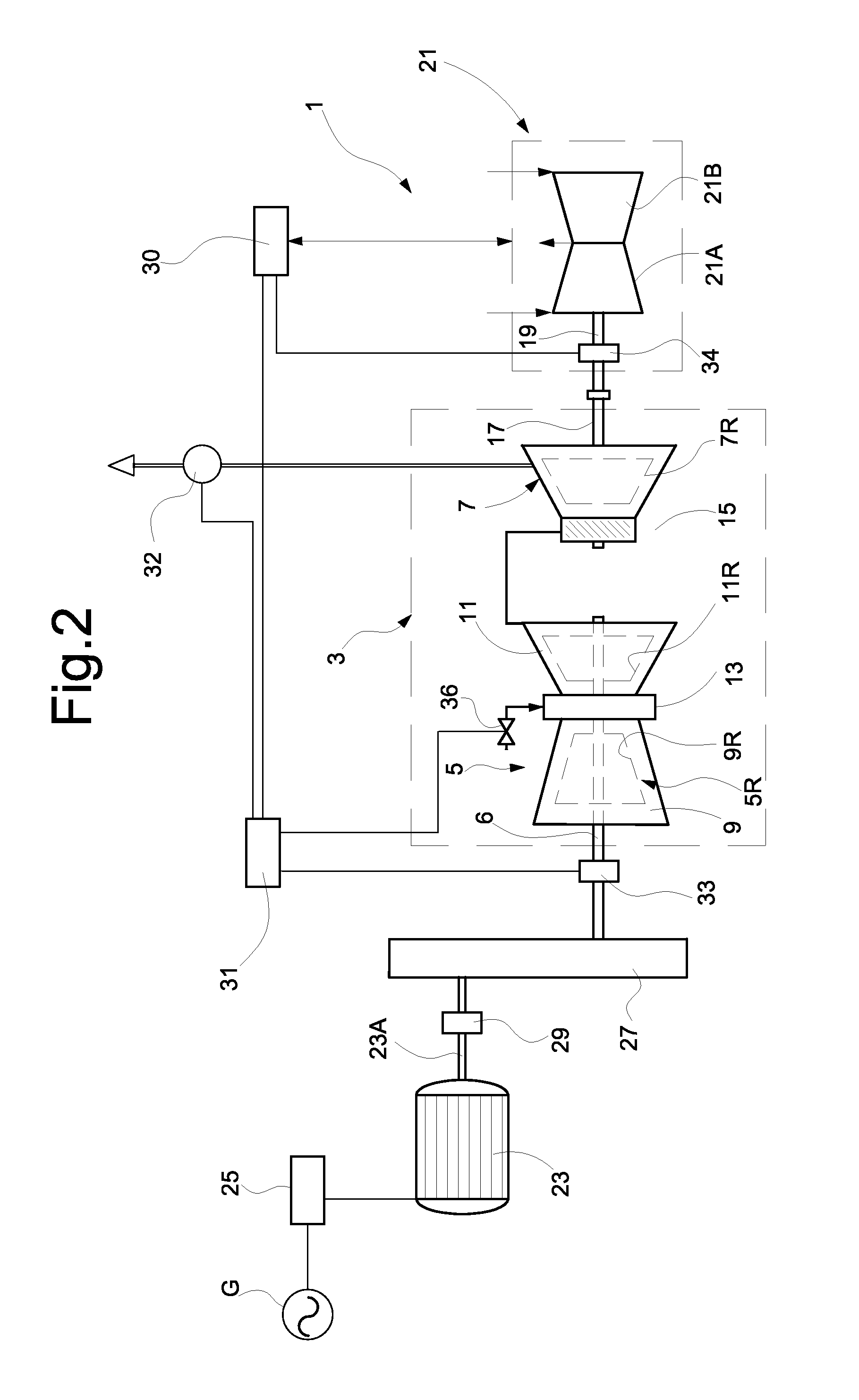
[0042]The following detailed description of the exemplary embodiments refers to the accompanying drawings. The same reference numbers in different drawings identify the same or similar elements. Additionally, the drawings are not necessarily drawn to scale. Also, the following detailed description does not limit the invention. Instead, the scope of the invention is defined by the appended claims.

[0043]Reference throughout the specification to “one embodiment” or “an embodiment” or “some embodiments” means that the particular feature, structure or characteristic described in connection with an embodiment is included in at least one embodiment of the subject matter disclosed. Thus, the appearance of the phrase “in one embodiment” or “in an embodiment” or “in some embodiments” in various places throughout the specification is not necessarily referring to the same embodiment(s). Further, the particular features, structures or characteristics may be combined in any suitable manner in one...


PUM


Abstract

A drive system for driving a load by a gas turbine. The gas turbine comprises a gas generator having a gas-generator rotor and comprising at least one gas-generator compressor and one high-pressure turbine driving the gas-generator compressor. The gas turbine further comprises a power turbine having a power-turbine rotor, which is torsionally independent of the gas-generator rotor. The load is connected to the power-turbine rotor. The system further comprises an electric motor / generator mechanically connected to the gas-generator rotor and electrically connected to an electric power grid. The electric motor / generator is adapted to function alternatively: as a generator for converting mechanical power from the gas turbine into electrical power; and as a motor for supplementing driving power to the load. A set of movable nozzle guide vanes is arranged at the inlet of the power turbine.

Description

BACKGROUND[0001]The subject matter disclosed herein concerns improvements to gas turbine systems used in mechanical drive applications. In particular, but not exclusively the disclosure concerns gas turbine systems for driving compressors, e.g. compressors for refrigerant fluids in liquefied natural gas facilities.[0002]The disclosure further concerns improvements in methods for operating a system comprising a gas turbine and a load, e.g. a compressor for LNG, or for oil and gas applications, a pump or other rotary equipment.[0003]Liquefied Natural Gas (LNG) results from a liquefaction process, in which the natural gas is cooled using one or more refrigeration cycles in a cascade arrangement, until it becomes liquid. Natural gas is often liquefied for storage or transportation purposes, e.g. if pipeline transportation is not possible or economically unfeasible.[0004]Cooling of the natural gas is performed using closed or opened refrigeration cycles. A refrigerant is processed in a c...

Claims


Application Information

Patent Timeline
IPC IPC(8): F02C6/00F01D15/10F02C9/20F02C9/28F02C3/05F02C7/275
CPCF02C6/00F02C3/05F02C7/275F05D2260/4023F02C9/28F01D15/10F05D2220/76F02C9/20F01D15/005F02C3/10F02C7/268F02C9/56
Inventor SANTINI, MARCO
Owner NUOVO PIGNONE SPA
Learn More