
Reversible bonding of microfluidic channels using dry adhesives

a technology of microfluidic channels and adhesives, applied in the direction of microstructural devices, microstructural technology, diaphragms, etc., can solve the problems of much earlier adhesive failure and problematic reversible bonding with pdms, and achieve the effect of improving reversible adhesion of the channel wall and reducing stress concentration

Active Publication Date: 2015-12-03
THE GOVERNORS OF THE UNIV OF ALBERTA
View PDF2 Cites 8 Cited by
  • Summary
  • Abstract
  • Description
  • Claims
  • Application Information

AI Technical Summary

Benefits of technology

This patent describes a reversible bonded microfluidic structure that has a strong resistance to leakage and can be easily integrated with electrodes. It uses an overhanging gasket structure atop a continuous microfluidic channel wall, which reduces stress concentrations and improves reversible adhesion with adjacent dry adhesive fibers. This structure can also be attached to any relatively smooth surface with minimal effort and can be integrated with CMOS or silicon MEMS with few modifications. Overall, this technology enhances the performance of the reversible bond in containing fluids and provides a reliable and flexible solution for fluidic applications.

Problems solved by technology

Unfortunately, reversible bonding with PDMS is also problematic, because the channels typically cannot hold desirably high fluid pressures for desired microfluidic applications.
This type of geometry is typically vulnerable to stress concentrations at the contact edge which will cause much earlier adhesive failure than the theoretical strength possible via van der Waals forces.

Method used


Image

  • Reversible bonding of microfluidic channels using dry adhesives
  • Reversible bonding of microfluidic channels using dry adhesives
  • Reversible bonding of microfluidic channels using dry adhesives

Examples


Embodiment Construction

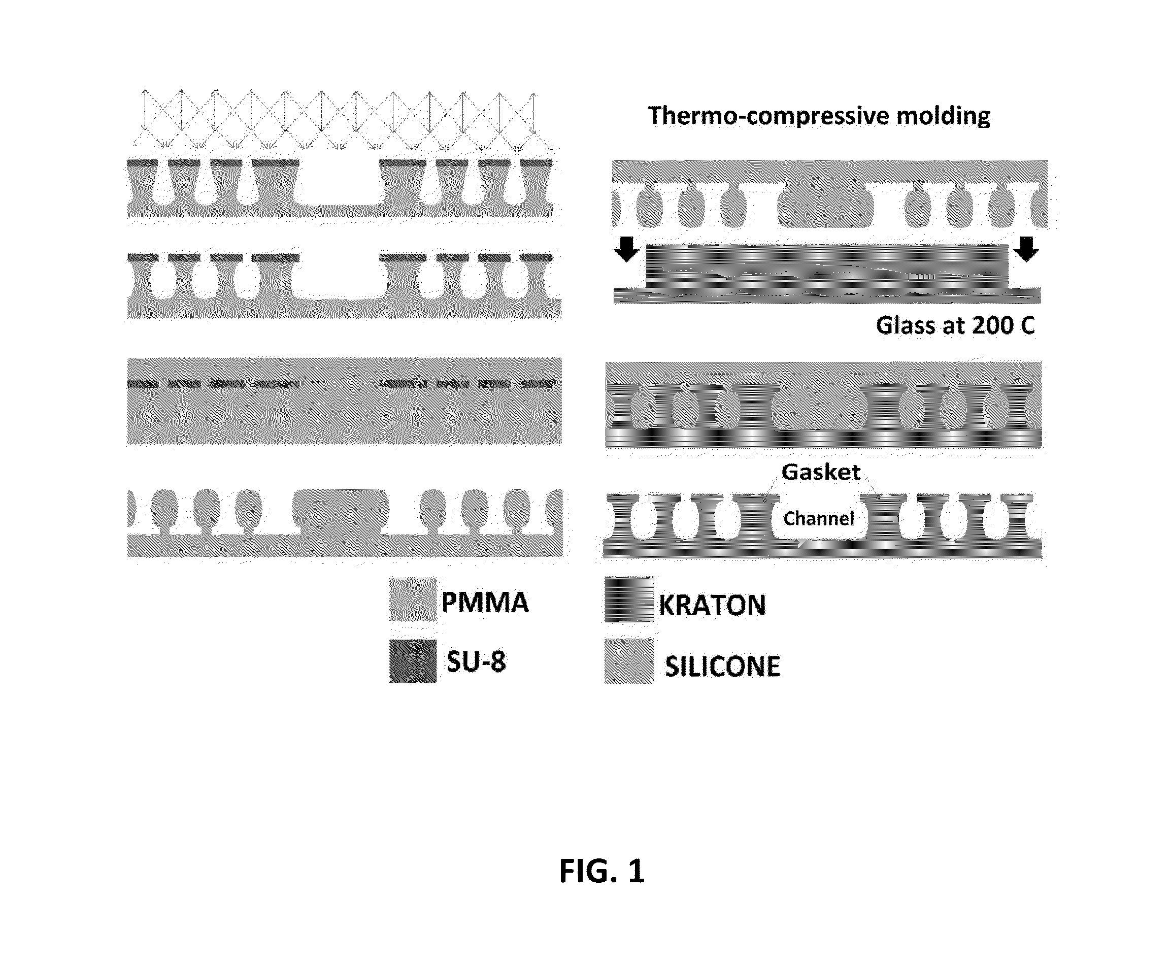
[0035]According to one embodiment of the present invention, a method of manufacturing a reversible bonded microfluidic structure is provided that uses semi-collimated UV light exposure to produce master molds for a reversible bonded microfluidic structure comprising one or more microfluidic channels having a continuous channel wall with overhanging gasket structure, and optionally also overhanging or interlocking dry adhesive structures substantially adjacent to the microfluidic channel wall gasket structures, to desirably provide for enhanced bonding to a suitable surface.

[0036]In one embodiment of the present invention, a fabrication method is provided that uses deep UV exposures such as from germicidal lamps or other suitable UV sources to convert commercial acrylic substrates (such as polymethylmethacrylate or “PMMA” for example) into master molds for reversible bonded microfluidic structures. Overhanging or interlocking microfluidic channel wall gasket structures and optional a...


PUM

PropertyMeasurementUnit
Flexibilityaaaaaaaaaa
Hydrophilicityaaaaaaaaaa

Abstract

A reversible bonded microfluidic structure comprises an overhanging cap or gasket structure atop a continuous microfluidic channel wall. An overhanging gasket structure may reduce stress concentrations at the edge of the channel wall and can permit improved reversible adhesion of the channel wall and adjacent dry adhesive fibers. In one example, reversible adhesion of the overhanging channel wall gasket and adjacent dry adhesive fibers may approach 1 MPa in axial loading. An overhanging gasket structure of the microfluidic channel wall may comprise a single “fiber” that is continuous around the perimeter of the desired microfluidic channel shape, and may define a self-sealing gasket which will contain fluid. The overhanging gasket structure may be surrounded by further overhanging or undercut dry adhesive fibers to enhance the adhesion and help make the rest of the surface more tolerant to defects and surface roughness.

Description

CROSS-REFERENCE TO RELATED APPLICATIONS[0001]The present application is a non-provisional application and claims priority to and benefit of U.S. Provisional Patent Application No. 62 / 004,090 filed May 28, 2014 and entitled REVERSIBLE BONDING OF MICROFLUIDIC CHANNELS USING DRY ADHESIVES, the contents of which are hereby incorporated by reference in their entirety for all purposes. This application further claims priority to and benefit of U.S. patent application Ser. No. 14 / 308,635 filed Jun. 18, 2014 and entitled COMPRESSION, EXTRUSION AND INJECTION MOLDING OF INTERLOCKING DRY ADHESIVE MICROSTRUCTURES WITH FLEXIBLE MOLD TECHNOLOGY, the contents of which are hereby incorporated by reference in their entirety for all purposes. This application also further incorporates by reference previously filed U.S. Provisional Patent Application No. 61 / 836,573 filed Jun. 18, 2013, and entitled COMPRESSION, EXTRUSION AND INJECTION MOLDING OF INTERLOCKING DRY ADHESIVE MICROSTRUCTURES WITH FLEXIBLE ...

Claims


Application Information

Patent Timeline
IPC IPC(8): B01L3/00B29C33/38B29C45/00B29C59/00B29C47/00B29C48/08
CPCB01L3/502715B29C59/00B29C47/0004B29C47/0028Y10T137/6851B29C33/3842B01L2400/0421B29L2022/00B29C45/00B29K2995/0098B29C33/3878B29C33/405B29C33/42B29C41/003B29K2833/12B29K2883/00B81C99/009Y10T428/23957B29L2007/00B29L2009/00B81C3/001B81B2201/058B29C48/08B29C48/022C09J2301/31
Inventor SAMEOTO, DANIEL ELLIOT
Owner THE GOVERNORS OF THE UNIV OF ALBERTA
Learn More