Delivery system for a prosthesis

a delivery system and prosthesis technology, applied in the field of prosthesis delivery systems, can solve the problems of increasing unnecessarily the complexity of construction and the passing diameter of the delivery system, and achieve the effect of reducing the amount and reducing the adverse effects of winding

Active Publication Date: 2015-12-03
CR BARD INC
View PDF2 Cites 0 Cited by
  • Summary
  • Abstract
  • Description
  • Claims
  • Application Information

AI Technical Summary

Benefits of technology

The patent is about a new design for a catheter delivery system for a self-expanding prosthesis, which simplifies the construction and improves the transfer of tensile stresses from the hand unit to the sheath surrounding the prosthesis. The system includes a fixation element made of heat shrink material, which circumscribes the pull wire and the catheter shaft, or slidable rings that slide along the shaft with the pull wire. This fixation element reduces the risk of winding of the pull wire around the shaft and mitigates the adverse effects of winding, if it occurs. The technical effects of this invention simplify the construction and improve the transfer of tensile stresses from the hand unit to the sheath surrounding the prosthesis.

Problems solved by technology

In the delivery systems hitherto, the pull element has been disposed within a lumen of the catheter shaft but the present inventors have realised that disposing the pull element in this way can increase unnecessarily the complexity of construction, and the passing diameter, of the delivery system.

Method used


Image

  • Delivery system for a prosthesis
  • Delivery system for a prosthesis

Examples


Embodiment Construction

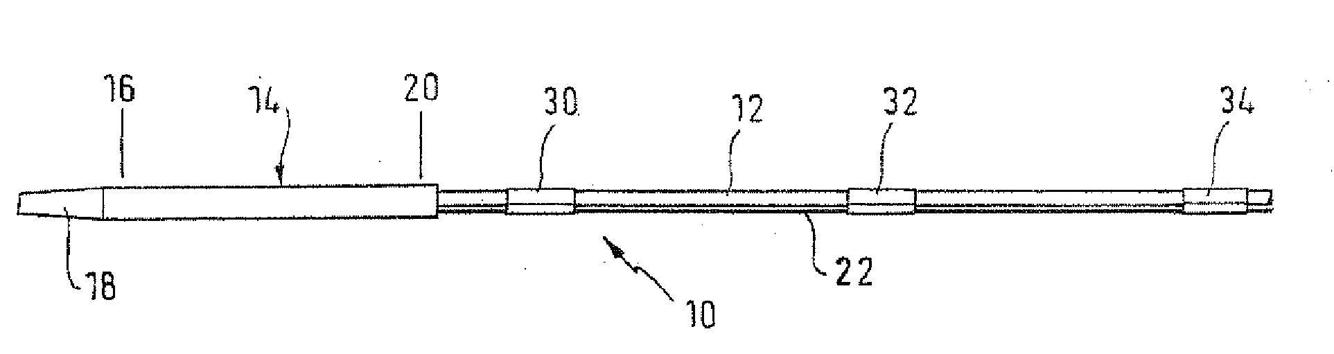
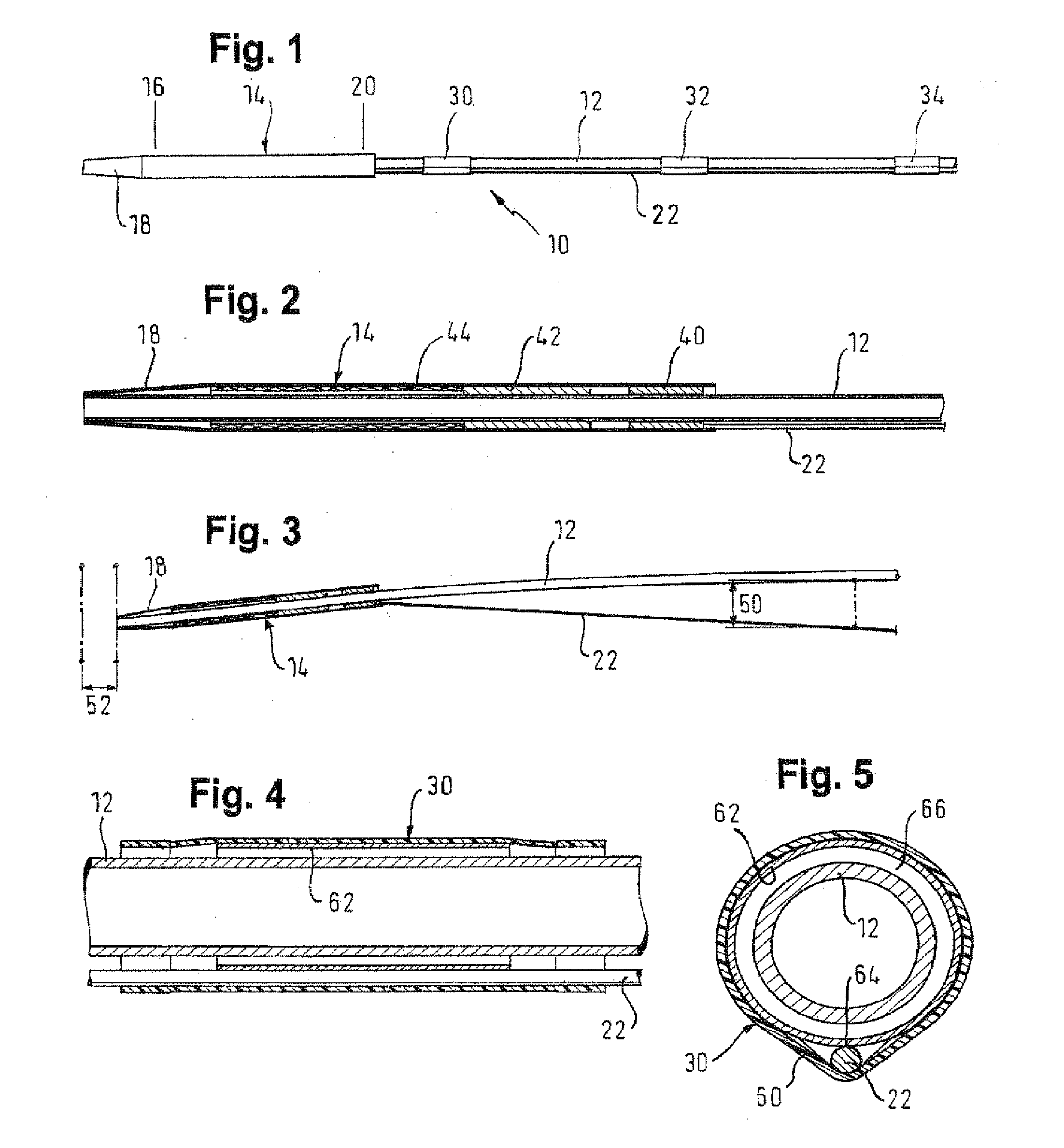
[0026]Looking first at FIG. 1, many of the components of the system will be familiar to those skilled in the art. The delivery system 10 of which the distal part is shown in FIG. 1 is based on a tube 12 which constitutes a catheter shaft. That tube carries at its distal end 14 a sheath 16 with a tapered tip 18 and a proximal end 20 within which lies (not visible in FIG. 1) an annulus to which is welded a pull wire 22. When the stent inside the sleeve 16 is to be deployed, tension is put on the pull wire 22 and this tension is passed through to the sheath 16 via the annulus within the proximal end 20 of the sheath. The sheath is pulled proximally, until its distal end 18 is proximal of the proximal end of the stent within the sheath 16, at which point to the stent is fully deployed and the delivery system can be withdrawn proximally out of the bodily lumen.

[0027]In FIG. 1, the catheter shaft is shown rigorously straight. However, in a typical placement within the human body, the shaf...


PUM


Abstract

The invention provides a delivery system for a prosthesis, said delivery system comprising a catheter shaft with a distal end, a proximal end and a longitudinal axis, a space for a prosthesis with a distal end and a proximal end, the space being at the distal end of the catheter shaft, a sheath with a proximal end and a distal end, the sheath being disposed at the distal end of the catheter shaft so as to surround the space, a pusher element attached to the distal end of the catheter shaft and arranged at the proximal end of the space for abutting prosthesis, a pull element with a longitudinal axis, the pull element running the length of the catheter shaft and having a distal end attached to the proximal end of the sheath and a proximal end for pulling the pull element proximally, thereby retracting the sheath proximally relative to the prosthesis space, and at least one fixation element having a proximal end and a distal end and being disposed within a flexible portion of the length of the shaft that lies between the proximal end of the sheath and the proximal end of the catheter shaft. The fixation element serves to limit a radial distance between the axis of the pull element outside the shaft and the axis of the catheter shaft along the length of the fixation element whenever a tensile stress in the pull element results in an endwise compressive stress on the shaft and a tendency of the shaft to bow, relative to the pull element.

Description

PRIORITY[0001]This application is a continuation of U.S. patent application Ser. No. 13 / 263,701, filed Dec. 19, 2011, now U.S. Pat. No. 9,107,771, which is a U.S. national stage application under 35 U.S.C. §371 of International Application No. PCT / EP2010 / 054592, filed Apr. 7, 2010, claiming priority to United Kingdom Patent Application No. 0906065.8, filed Apr. 7, 2009, and to U.S. Provisional Application No. 61 / 167,268, filed Apr. 7, 2009, each of which is incorporated by reference in its entirety into this application.TECHNICAL FIELD[0002]This invention relates to a delivery system for a prosthesis such as a self-expanding stent, the delivery system taking the form of a catheter that includes a sheath surrounding the stent, and a pull wire to pull the sheath proximally, progressively to release the stent.BACKGROUND[0003]The published literature includes a multitude of designs for stent delivery catheters that will deploy a self-expanding stent, such as one made out of nickel titan...

Claims


Application Information

Patent Timeline
Patent Type & Authority Applications(United States)
IPC IPC(8): A61F2/966A61F2/95
CPCA61F2002/9522A61F2/966A61F2220/0033A61F2/011A61F2/9522A61F2/958A61F2002/9665A61F2/856A61F2/89A61F2002/823
Inventor WUEBBELING, MARTINMAIR, JUTTA
Owner CR BARD INC
Why Eureka
Try Eureka