Current Collector For A Lithium Battery

Inactive Publication Date: 2015-11-26
COMMISSARIAT A LENERGIE ATOMIQUE ET AUX ENERGIES ALTERNATIVES
View PDF2 Cites 6 Cited by
  • Summary
  • Abstract
  • Description
  • Claims
  • Application Information

AI Technical Summary

Benefits of technology

The patent text describes a new design for a polymer foam-based lithium-ion battery cell that improves its performance and safety. The cell includes a polymer film with fillers that increase its rigidity and a metal frame that can be sealed tightly using laser welding. The design also improves the contact between the electrode and collector, which helps to improve the cell's power performance. Overall, this design helps to create a more robust and reliable lithium-ion battery cell.

Problems solved by technology

Indeed, prior art Li-ion cells generally comprise materials which may deform during the cycling, and also cause the forming of gas.

Method used


Image

  • Current Collector For A Lithium Battery
  • Current Collector For A Lithium Battery
  • Current Collector For A Lithium Battery

Examples


Embodiment Construction

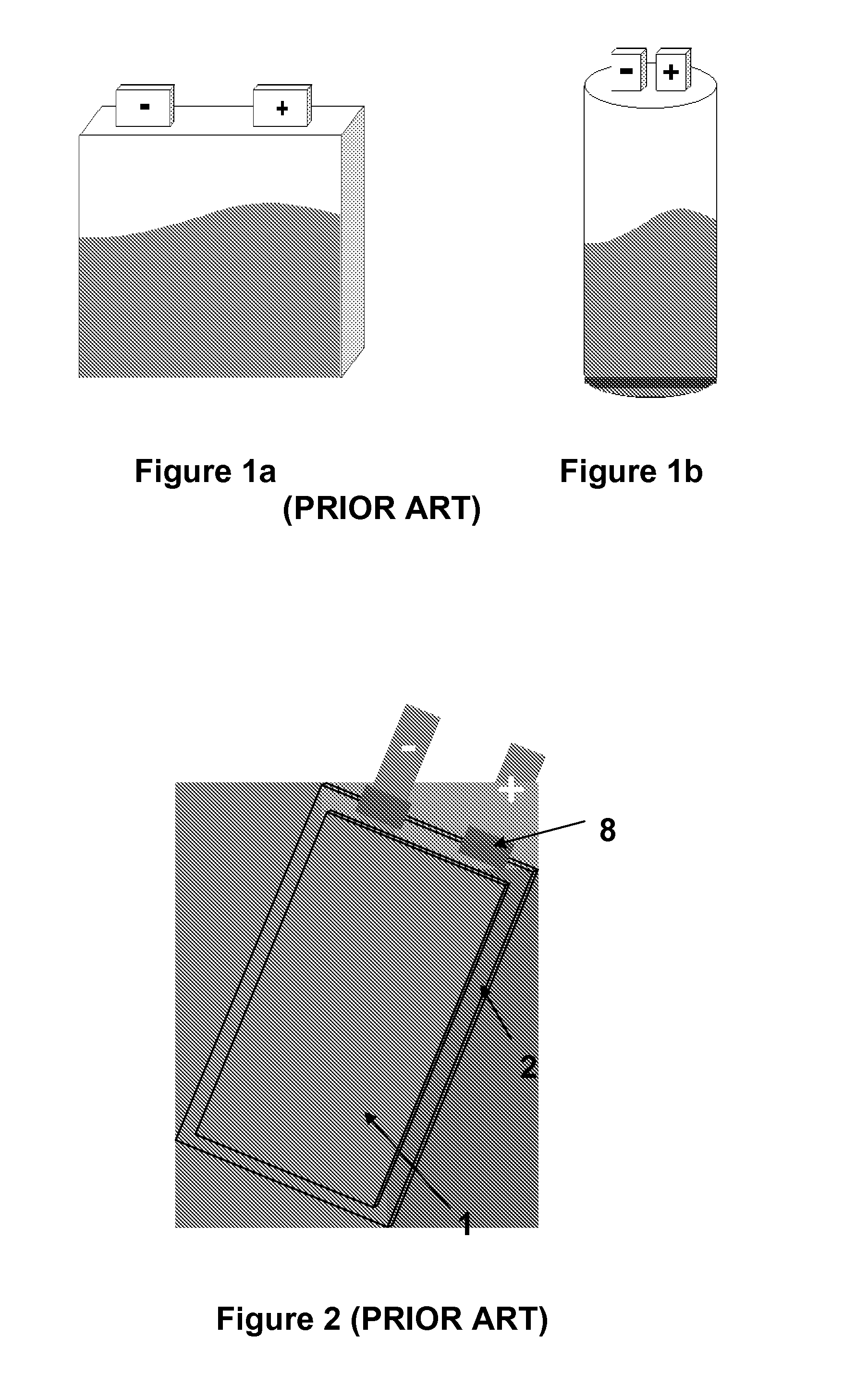
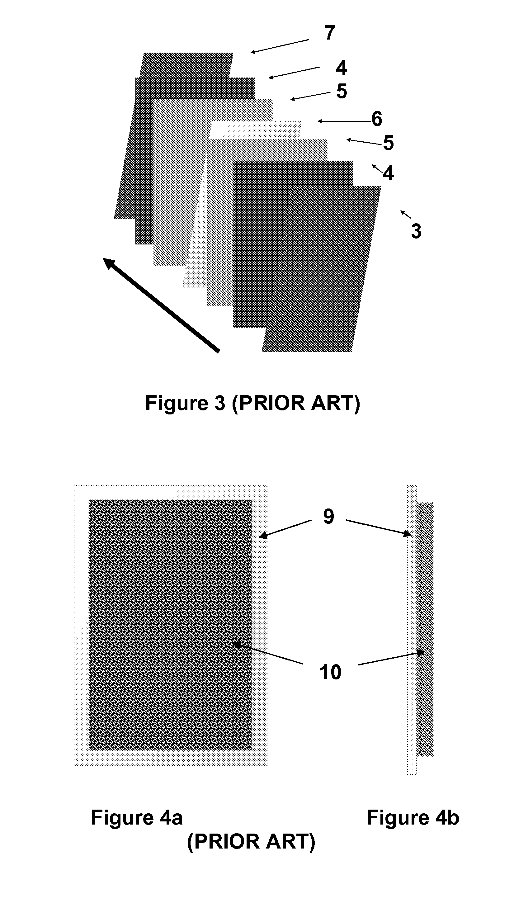
[0071]Prior art Li-ion cells having a flexible package (FIG. 2) are generally formed of a cell core (1) coated with a flexible multilayer package (2). The multilayer (2) is typically formed of the association, from the inside to the outside of the cell (FIG. 3), of the following layers:[0072]a polyolefin layer (3) having an approximate 50-micrometer thickness;[0073]a glue layer (4);[0074]a so-called foundation layer (5);[0075]an aluminum foil (6) having an approximate 40-micrometer thickness;[0076]a so-called foundation layer (5);[0077]a glue layer (4);[0078]a polyolefin layer (7) having an approximate 20-micrometer thickness.

[0079]Further, in this type of cells, the connection between the electrodes and the positive and negative poles is generally consolidated by a polymer reinforcement (8) (FIG. 2).

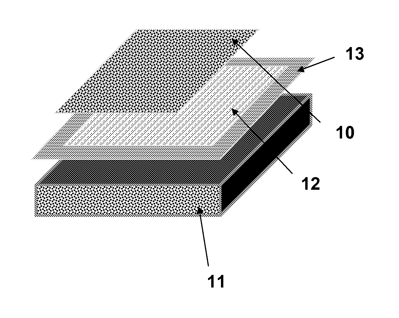
[0080]Prior art Li-ion cells are generally formed of a metallic (aluminum) current collector (9) having the electrode material (10) deposited thereon (FIG. 4).

[0081]Electrode material p...


PUM

PropertyMeasurementUnit
Temperatureaaaaaaaaaa
Fractionaaaaaaaaaa

Abstract

This current collector for a lithium electrochemical accumulator includes an electronically-insulating viscoelastic foam associated with an electroconductive polymer film.

Description

FIELD OF THE INVENTION[0001]The invention relates to a current collector for an electrochemical lithium battery or accumulator. Such a current collector comprising a viscoelastic foam also ensures the accumulator packaging function.BACKGROUND OF THE INVENTION[0002]Electrochemical lithium accumulators operate based on the principle of lithium insertion or deinsertion (or intercalation-deintercalation) on at least one electrode.[0003]They comprise an electrochemical anode / electrolyte / cathode core which may be integrated in a structure having a cylindrical, prismatic, or stacked geometry, for example. The two electrodes each comprise a current collector and are separated by a separator which can appear in solid or polymeric form (membrane).[0004]Generally, the accumulator core is protected from external elements by a rigid or flexible package.[0005]The accumulator may thus be contained in a metal package (FIG. 1), for example, made of aluminum. This type of package is generally designe...

Claims


Application Information

Patent Timeline
IPC IPC(8): H01M4/66H01M4/04
CPCH01M4/667H01M4/668Y10T156/10H01M4/0414H01M10/0525H01M4/0404H01M4/386H01M4/505H01M4/525H01M4/5825H01M10/052Y02E60/10H01M4/13
Inventor CHAMI, MARIANNEJOUANNEAU-SI LARBI, SEVERINE
Owner COMMISSARIAT A LENERGIE ATOMIQUE ET AUX ENERGIES ALTERNATIVES
Why Eureka
Try Eureka