Electrochromic display element, display device, information system, and electrochromic dimming lens

a technology of display elements and electrochromic dimming, which is applied in non-linear optics, instruments, optics, etc., can solve the problems of reducing the light fastness of an electrochromic display element, the coating of polymer compounds cannot sufficiently suppress the photocatalystic activity of titanium oxide particles, and the reduction of light fastness. , to achieve the effect of excellent color discharging, excellent light fastness and excellent color fastness

Active Publication Date: 2015-11-19
RICOH KK
View PDF9 Cites 28 Cited by
  • Summary
  • Abstract
  • Description
  • Claims
  • Application Information

AI Technical Summary

Benefits of technology

[0015]The present invention aims to provide an electrochromic display element, which has excellent light fastness, and excellent coloring-discharging properties
[0016]The present invention aims to provide an electrochromic display element having excellent light fastness, and excellent coloring-discharging properties in a reflective display system and a transmissive display system, without increasing voltage required for coloring and discharging.
[0026]The present invention can solve the aforementioned various problems in the art, achieve the aforementioned object, and provide an electrochromic display element having excellent light fastness, and excellent coloring-discharging properties in a reflective display system and a transmissive display system, without increasing voltage required for coloring and discharging.

Problems solved by technology

However, titanium oxide, which is a photocatalystic active material, decomposes an electrochromic compound, and other constituting elements, to thereby reduce light fastness of an electrochromic display element.
Use of rutile-type titanium oxide is proposed as the measure for preventing photocatalystic activities of the titanium oxide, but it is difficult to suppress reduction of the light fastness.
However, the disclosed coating of the polymer compound cannot sufficiently suppress photocatalystic activities of the titanium oxide particles.
Moreover, there is also a problem that no measure for suppressing the photocatalystic activities is provided on the titanium oxide particles used as bearing particles of the electrochromic compound.

Method used


Image

  • Electrochromic display element, display device, information system, and electrochromic dimming lens
  • Electrochromic display element, display device, information system, and electrochromic dimming lens
  • Electrochromic display element, display device, information system, and electrochromic dimming lens

Examples


example 1

Production of Electrochromic Device

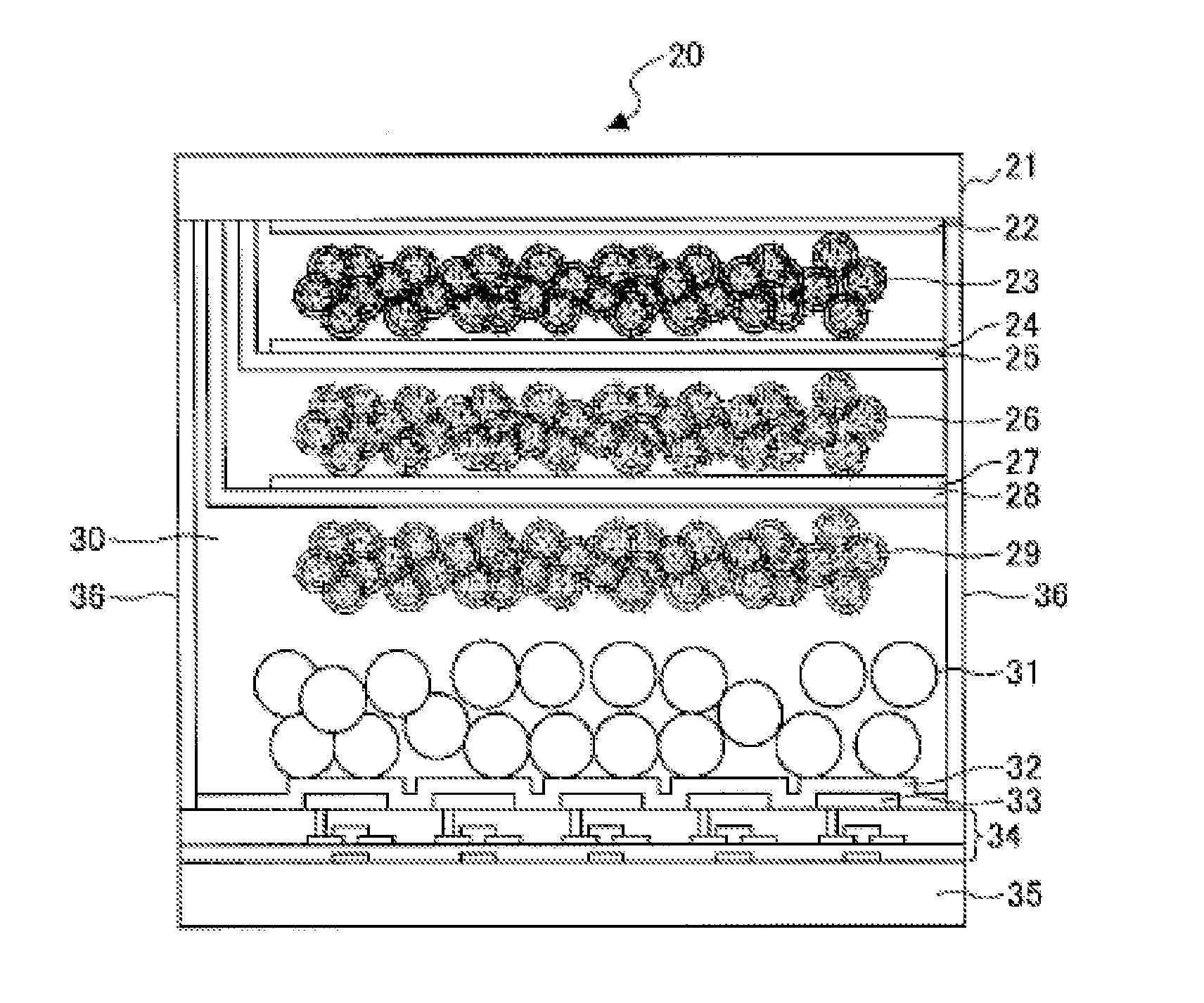
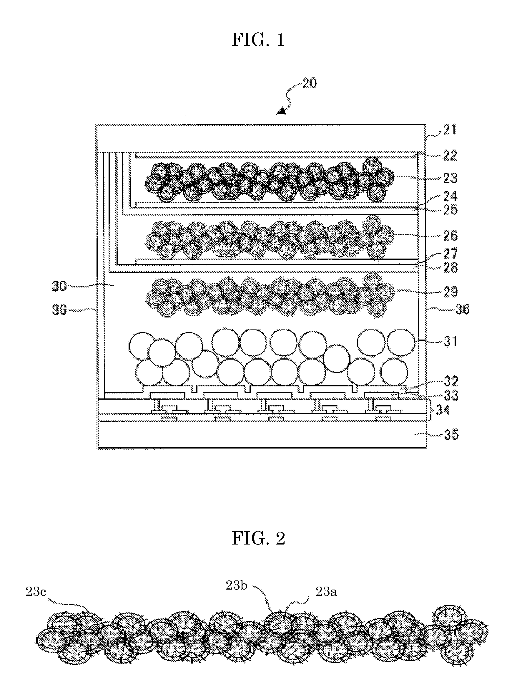
[0313]In Example 1, an example of a production of an electrochromic device 20 illustrated in FIG. 1 is depicted. Note that, the electrochromic device 20 produced in Example 1 can be also used as a dimming glass device.

—Formation of First Display Electrode—

[0314]First, an Ito film having a thickness of about 100 nm, and surface resistance of about 200 Ω / sq. was formed on a glass substrate in the size of 400 nm in length×400 nm in width, serving as a display substrate 21, through sputtering, to thereby form a first display electrode 22.

—Formation of First Electrochromic Layer—

[0315]Subsequently, a dispersion liquid of titanium oxide particles, in which aluminum hydroxide (amount of aluminium hydroxide: 7.7% by mass, the average particle diameter: 20 nm) was dispersed at inner parts and on surfaces thereof was applied onto the first display electrode 22 by spin coating. Thereafter, annealing was performed at 120° C. for 15 minutes to thereby partially...

example 2

Production of Electrochromic Device

[0348]An electrochromic display element illustrated in FIG. 1 was produced in the same manner as in Example 1, provided that titanium oxide particles having the average particle diameter of 300 nm and free from aluminum hydroxide were used as the titanium oxide particles contained in the white reflection layer.

[0349]Subsequently, light fastness of the produced electrochromic display element of Example 2 was evaluated in the same manner as in Example 1, by measuring a color difference retention rate. Moreover, the coloring voltage and discharging voltage were measured in the same manner as in Example 1. These results are presented in Table 1.

[0350]The color difference ΔE_α before the light irradiation was 54.9.

[0351]The color difference ΔE_β after the light irradiation was 35.9.

[0352]Specifically, in the case where the titanium oxide particles, in the inner parts and on the surfaces of which aluminum hydroxide was dispersed were used as the titanium...

example 3

Production of Electrochromic Device

[0354]An electrochromic display element illustrated in FIG. 1 was produced in the same manner as in Example 1, provided that titanium oxide particles having the average particle diameter of 20 nm and free from aluminum hydroxide were used as the titanium oxide particles contained in the electrochromic layer.

[0355]Subsequently, light fastness of the produced electrochromic display element of Example 3 was evaluated in the same manner as in Example 1, by measuring a color difference retention rate. Moreover, the coloring voltage and discharging voltage were measured in the same manner as in Example 1. These results are presented in Table 1.

[0356]The color difference ΔE_α before the light irradiation was 52.8.

[0357]The color difference ΔE_β after the light irradiation was 23.7.

[0358]Specifically, in the case where the titanium oxide particles, in the inner parts and on the surfaces of which aluminum hydroxide was dispersed, were used as the titanium o...


PUM

PropertyMeasurementUnit
lengthaaaaaaaaaa
particle diameteraaaaaaaaaa

Abstract

To provide an electrochromic display element, which contains: a display substrate; a display electrode; an electrochromic layer provided in contact with the display electrode; a counter substrate provided to face the display substrate; a counter electrode; a charge retention layer provided in contact with the counter electrode; and an electrolyte layer filling between the display substrate and the counter substrate, wherein the electrochromic layer contains titanium oxide particles, and metal hydroxide is dispersed on surfaces and in inner parts of the titanium oxide particles.

Description

BACKGROUND OF THE INVENTION[0001]1. Field of the Invention[0002]The present invention relates to an electrochromic display element, a display device, information equipment, and an electrochromic dimming lens.[0003]2. Description of the Related Art[0004]As for an electronic medium replacing paper, developments of electronic paper have been recently actively carried out. Examples of a display element used for the electronic paper include a display element using reflecting liquid crystals, a display element using electrophoresis, a display element using toner migration, and a display element using an electrochromic compound (an electrochromic display element).[0005]The electrochromic display element is a strong candidate for a display element of the next generation, because it has a memory effect, and can be driven at low voltage. Therefore, a wide range of researches and developments have been currently conducted on the electrochromic display element, including a development of a mate...

Claims


Application Information

Patent Timeline
Patent Type & Authority Applications(United States)
IPC IPC(8): G02F1/15G02F1/153G02F1/155G02F1/1524
CPCG02F1/1523G02F1/155G02F2001/1536G02F2001/1555G02F1/1533G02F1/1347G02F1/1524G02F1/15245
Inventor TAKAHASHI, HIROYUKIHORIUCHI, TAMOTSUYASHIRO, TOHRUYUTANI, KEIICHIROHOKADA, YOSHINORIKIM, SUKCHANFUJIMURA, KOHNAIJO, YOSHIHISATSUJI, KAZUAKIHIRANO, SHIGENOBUSAGISAKA, TOSHIYAINOUE, MAMIKOYAMAMOTO, SATOSHIGOTO, DAISUKE
Owner RICOH KK
Why Eureka
Try Eureka