Imaging apparatus for diagnosis, information processing apparatus, control method thereof, program and computer-readable storage medium

Active Publication Date: 2015-11-12
TERUMO KK
View PDF2 Cites 3 Cited by
  • Summary
  • Abstract
  • Description
  • Claims
  • Application Information

AI Technical Summary

Benefits of technology

The patent describes a way for doctors to monitor the progress of a patient after a stent has been placed without having to perform a complicated procedure. This makes it easier for healthcare professionals to monitor the patient's recovery and take appropriate measures if needed.

Problems solved by technology

However, when the three-dimensional image is used to display the postoperative progress, a diagnostician has to check the three-dimensional image by setting various viewpoint positions, thereby causing a relatively complicated operation.
Consequently, a high-level response to a user's operation cannot be expected.

Method used


Image

  • Imaging apparatus for diagnosis, information processing apparatus, control method thereof, program and computer-readable storage medium
  • Imaging apparatus for diagnosis, information processing apparatus, control method thereof, program and computer-readable storage medium
  • Imaging apparatus for diagnosis, information processing apparatus, control method thereof, program and computer-readable storage medium

Examples


Embodiment Construction

[0024]According to the present description, postoperative progress can be relatively easily checked without a need to perform a complicated operation after a stent indwells.

[0025]Hereinafter, an embodiment according to the present disclosure will be described in detail with reference to the accompanying drawings.

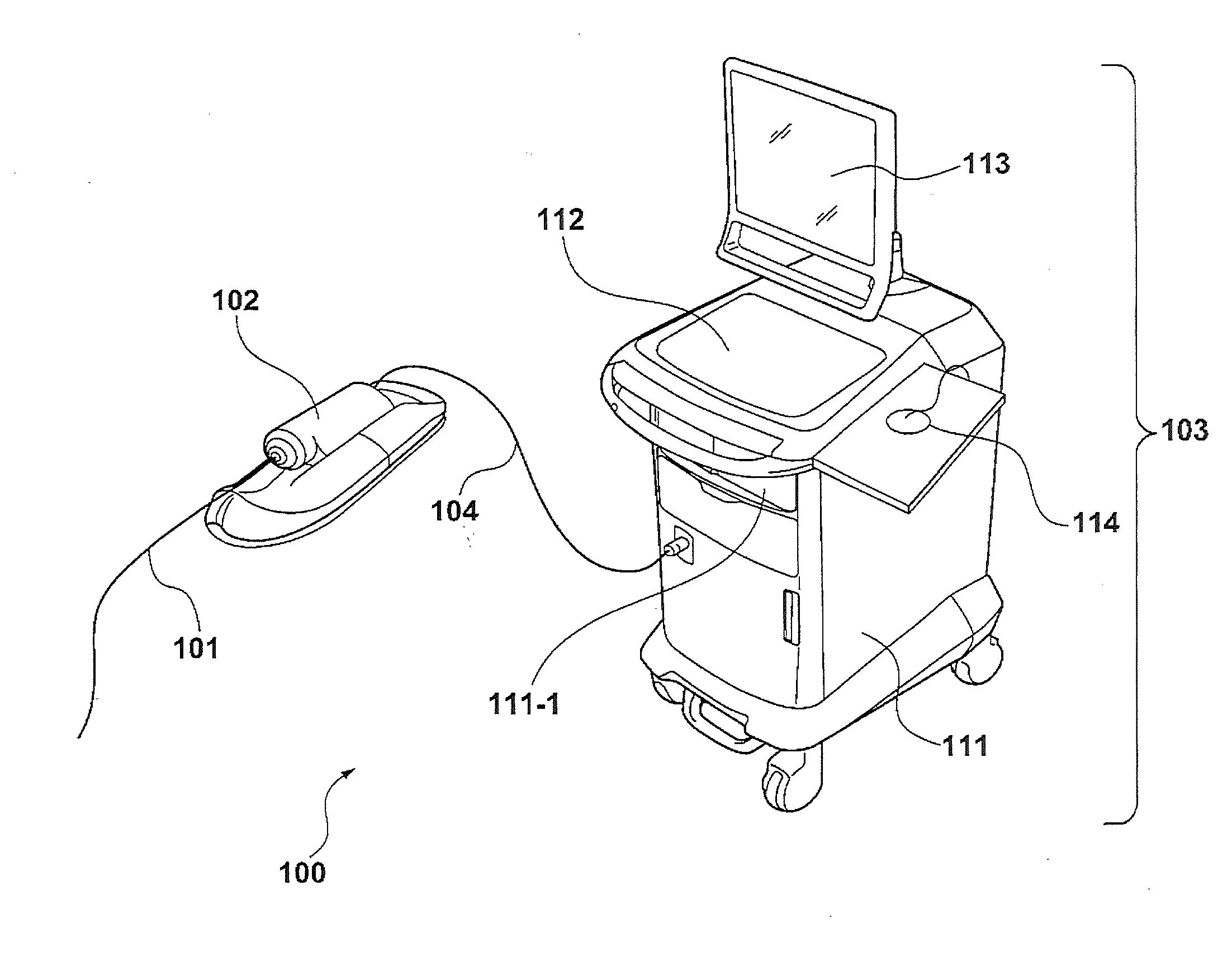
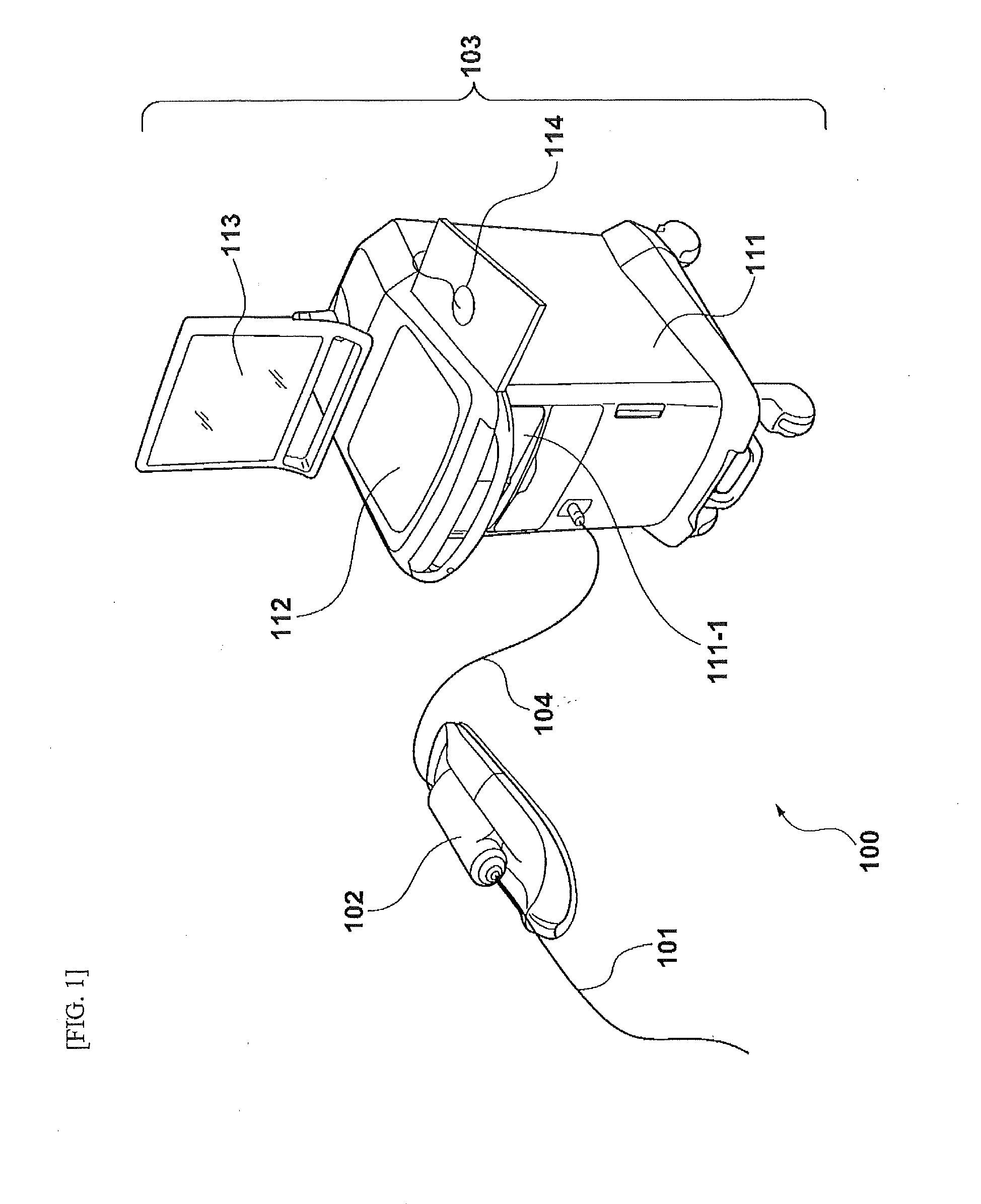
[0026]FIG. 1 is a view illustrating an external configuration of an imaging apparatus for diagnosis 100 according to an embodiment of the present disclosure.

[0027]As illustrated in FIG. 1, the imaging apparatus for diagnosis 100 can includes a probe unit 101, a scanner and pull-back unit 102, and an operation control device 103. The scanner and pull-back unit 102 and the operation control device 103 can be connected to each other by a signal line 104 so that various signals can be transmitted.

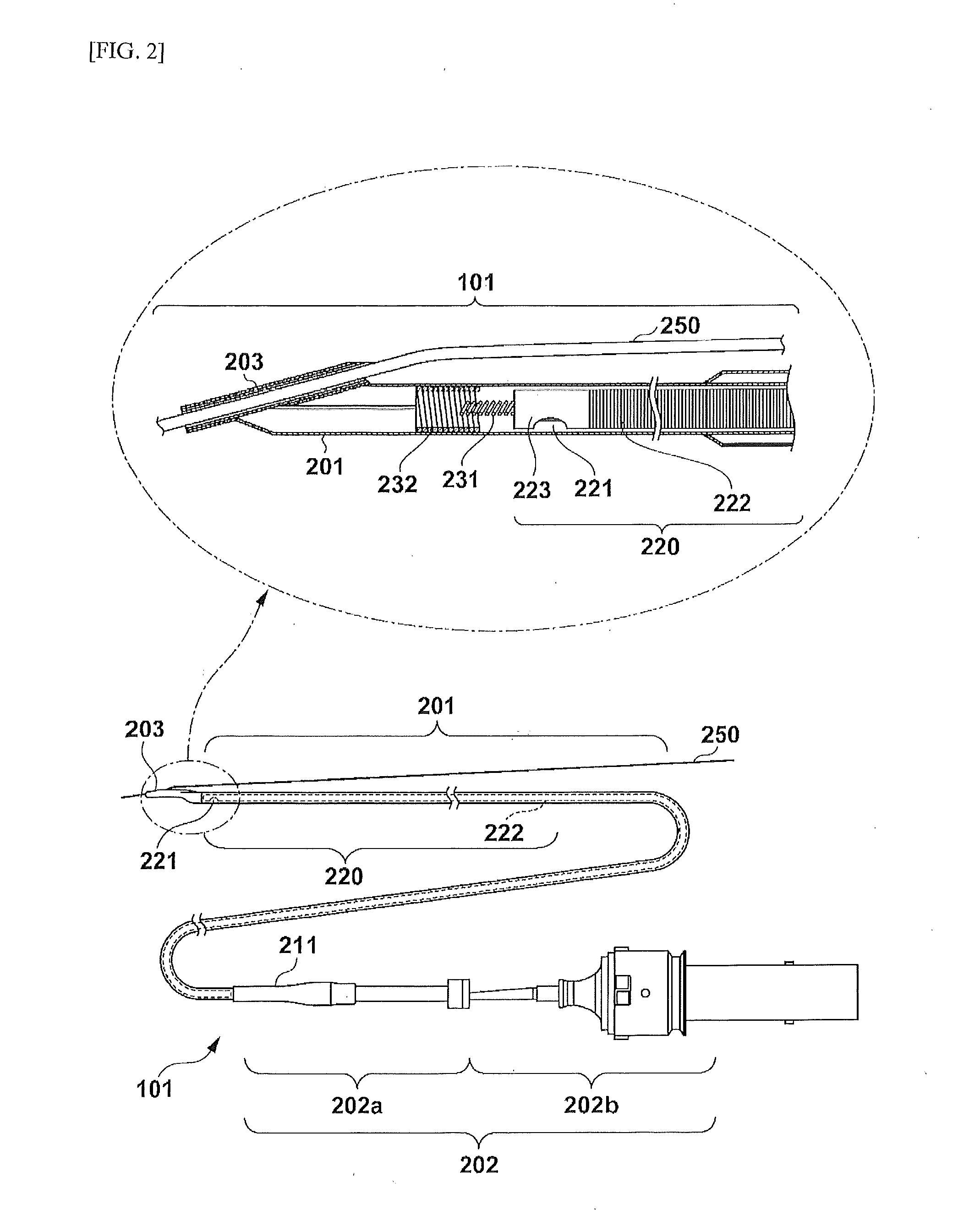
[0028]The probe unit 101 has an internally inserted imaging core which is directly inserted into a blood vessel and includes an optical transceiver which continuously transmits transmit...


PUM


Abstract

An imaging apparatus for diagnosis and a control method of an imaging apparatus for diagnosis are disclosed, which acquire line data represented by multiple luminance values in a radial direction from a rotation center position of an imaging core, which are derived by a rotation position and movement of the imaging core. Then, based on the acquired line data, an image of a two-dimensional space in which θ representing a rotation angle and z representing a position in a movement direction are set to two axes is generated and displayed.

Description

RELATED APPLICATION(S)[0001]This application is a continuation of International Application No. PCT / JP2013 / 000327 filed on Jan. 23, 2013, the entire content of which is incorporated herein by reference.FIELD[0002]The present disclosure relates to a technique for generating a tomographic image of biological tissues by using light.BACKGROUND INFORMATION[0003]Intravascular treatment has been carried out by using a highly functional catheter such as a balloon catheter, a stent, or the like. An imaging apparatus for diagnosis such as an optical coherence tomography (OCT) apparatus has been generally used in order to perform preoperative diagnosis or to check postoperative progress.[0004]The optical coherence tomography apparatus includes a built-in optical fiber, to a distal end of which an imaging core having an optical lens and an optical mirror is attached. At least a distal end portion of the optical fiber has a transparent sheath. Then, the sheath is inserted into a blood vessel of ...

Claims


Application Information

Patent Timeline
IPC IPC(8): A61B5/00G06T7/00A61B5/02G06T11/00
CPCA61B5/0066G06T11/003G06T7/0002A61B5/742A61B2576/02G06T2207/30101G06T2207/10072G06T2211/40A61B5/02007A61B5/0084A61B5/06G16H30/40A61B1/000094A61B5/6852
Inventor FURUICHI, JUNYAINOUEETOU, HIJIRI
Owner TERUMO KK
Why Eureka
Try Eureka