Image forming apparatus and image forming method
- Summary
- Abstract
- Description
- Claims
- Application Information
AI Technical Summary
Benefits of technology
Problems solved by technology
Method used
Image
Examples
first embodiment
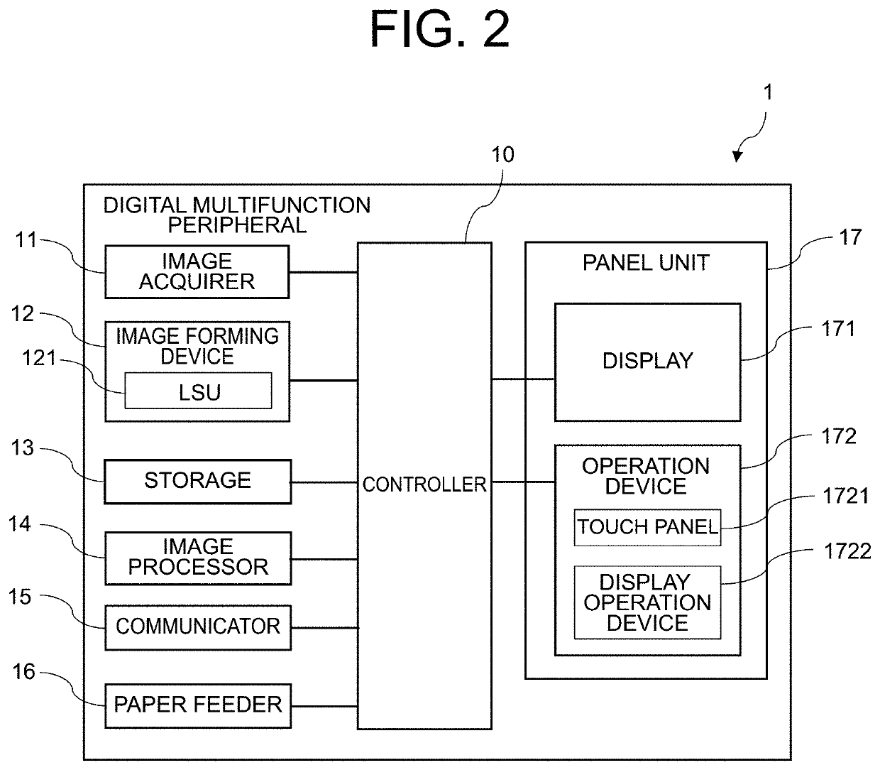
[0033]A description will be made on a digital multifunction peripheral 1 as an embodiment of the image forming apparatus according to the present invention with reference to FIG. 1 and FIG. 2.
[0034]FIG. 1 is a perspective view of external appearance of the digital multifunction peripheral 1 according to a first embodiment of the present invention. FIG. 2 is a block diagram of a schematic configuration of the digital multifunction peripheral 1 illustrated in FIG. 1.
[0035]The present invention is not limited to the digital multifunction peripheral 1 and can be applied to all types of equipment that have an image data acquiring (receiving) function and an image data transmitting function such as a scanner, a fax machine, and an electronic mail.
[0036]The digital multifunction peripheral 1 is an apparatus such as a multifunction peripheral (MFP) that executes digital processing of image data and has a copier function, a scanner function, and a facsimile function.
[0037]The digital multifu...
second embodiment
[0099]Next, a description will be made on image data editing processing by a digital multifunction peripheral 1 according to a second embodiment of the present invention with reference to FIGS. 7A and 7B.
[0100]FIGS. 7A and 7B include explanatory views of a specific example of the image data editing processing by the digital multifunction peripheral 1 according to the second embodiment of the present invention.
[0101]As illustrated in FIG. 7A, when the display 171 displays the list of the first page of DATA 1 and the first page and the third page of DATA 2, the user cancels the selection of the image of the first page of DATA 2 (OPERATION 1).
[0102]At this time, the image of the first page of DATA 2 is deleted from the display 171, and the display 171 displays a list of the images of the remaining pages (the first page of DATA 1 and the third page of DATA 2).
[0103]In FIG. 7B, when the user presses the “PRINT” button (OPERATION 2), the job for the images of the remaining pages is execut...
third embodiment
[0105]Next, a description will be made on image data editing processing by a digital multifunction peripheral 1 according to a third embodiment of the present invention with reference to FIGS. 8A to 8C.
[0106]FIGS. 8A to 8C include explanatory views of a specific example of the image data editing processing by the digital multifunction peripheral 1 according to the third embodiment of the present invention.
[0107]As illustrated in FIG. 8A, when the display 171 displays the list of the first page of DATA 1 and the first page and the third page of DATA 2, the user slides (swipes) the image of the first page of DATA 1 to the right while pressing such an image, so as to move the first page of DATA 1 between the first page of DATA 2 and the third page of DATA 2 (OPERATION 1).
[0108]At this time, as illustrated in FIG. 8B, the display 171 displays that the image of the first page of DATA 1 and the image of the first page of DATA 2 are switched.
[0109]Thereafter, in FIG. 8C, when the user pres...
PUM
 Abstract
Description
Claims
Application Information
 - R&D
- Intellectual Property
- Life Sciences
- Materials
- Tech Scout
- Unparalleled Data Quality
- Higher Quality Content
- 60% Fewer Hallucinations
Browse by: Latest US Patents, China's latest patents, Technical Efficacy Thesaurus, Application Domain, Technology Topic, Popular Technical Reports.
© 2025 PatSnap. All rights reserved.Legal|Privacy policy|Modern Slavery Act Transparency Statement|Sitemap|About US| Contact US: help@patsnap.com


