
Multi-material three dimensional printer

Inactive Publication Date: 2015-11-05
EOPLEX
View PDF7 Cites 76 Cited by
  • Summary
  • Abstract
  • Description
  • Claims
  • Application Information

AI Technical Summary

Benefits of technology

The invention is about a 3D printer that can create objects with different materials and void spaces. The printer can print complete objects or treat them to make them stronger. The treatment involves removing the binder material and densifying the powders to make them similar to the solid material they are derived from. This allows the objects to have properties that make them useful in their own right. The printer can also create objects that have a void space filled with another material.

Problems solved by technology

While these different filaments do represent different types of polymeric materials, the technique is limited to low melting point, largely organic materials.
Because FDM printers require the print head to trace every voxel in a 3D model, one voxel at a time, and at rates compatible with melting and extruding material, they are quite slow to produce an object of any significant volume.
None of the current systems are capable of creating an object with different regions of the object comprised of different material.

Method used


Image

  • Multi-material three dimensional printer
  • Multi-material three dimensional printer
  • Multi-material three dimensional printer

Examples


Embodiment Construction

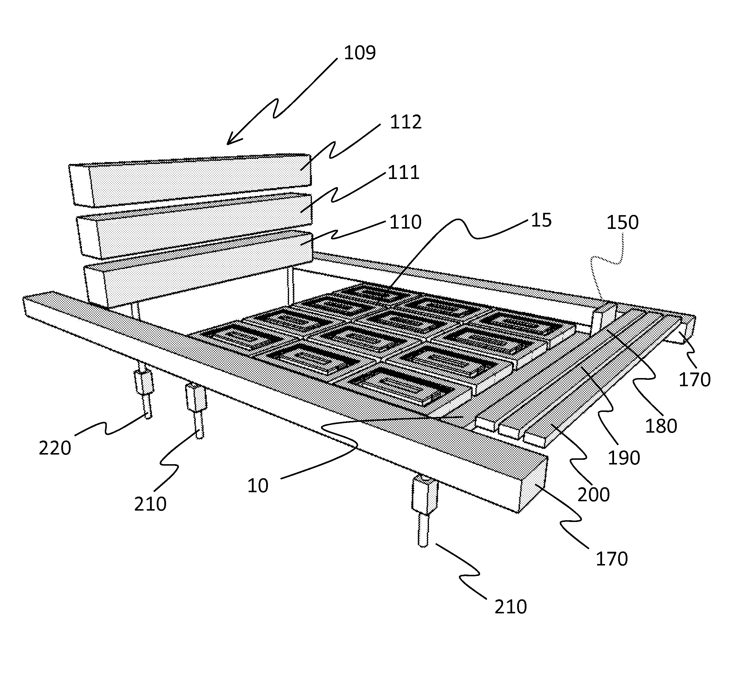
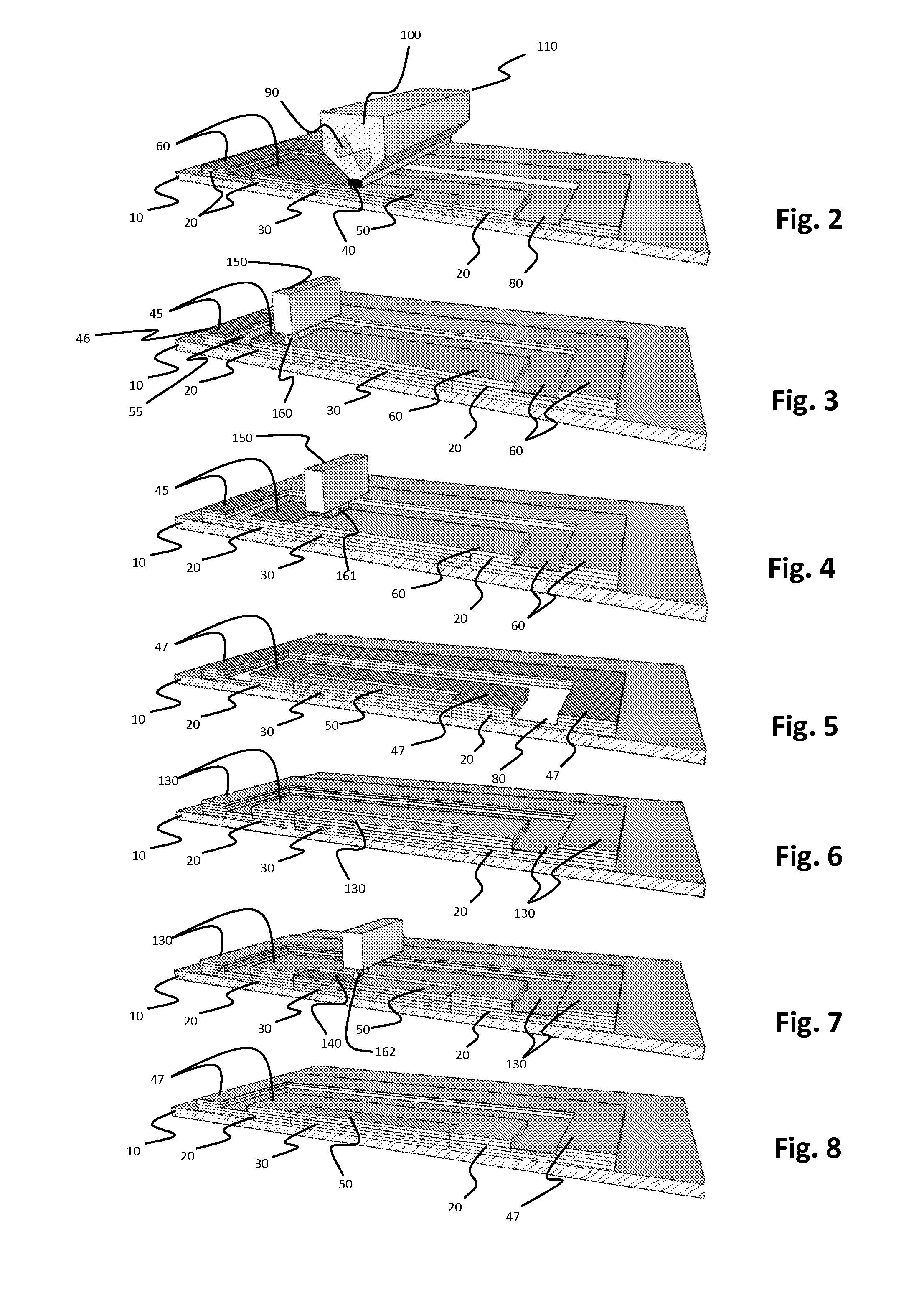
[0036]Referring to the drawings, wherein like reference numerals represent like parts throughout the various drawing figures, this invention is directed to a printer which prints in three dimensions with multiple materials. The printer includes a build plate 10 (FIG. 9) upon which an object or array of objects 15 are built in sequential layers. Each completed layer can be formed of a first material 20 and a second material 30 (and additional materials) limited to different portions thereof. Voids can also be provided within individual layers by filling such portions of the layers with fugitive material which is later removed.

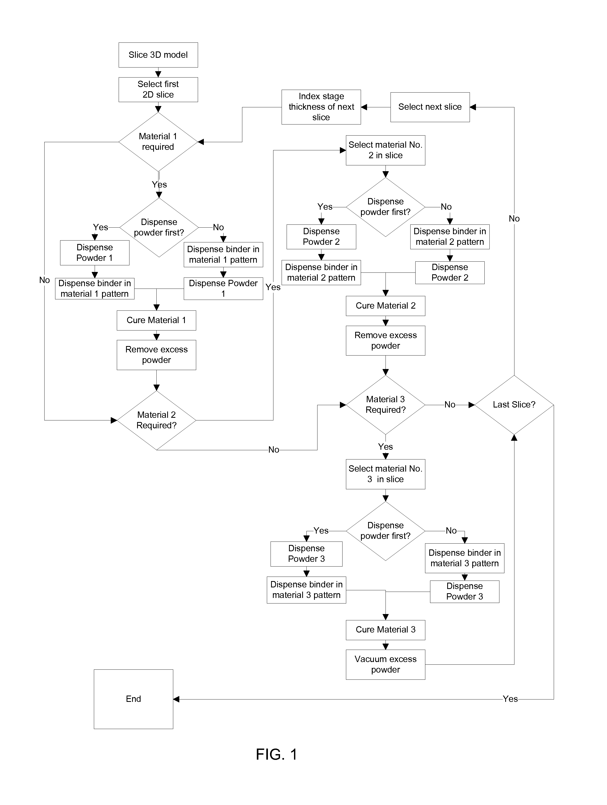
[0037]The basic process implemented by this invention is depicted in the flow chart of FIG. 1. First, an object to be printed begins as a three dimensional model and is sliced into multiple two dimensional slices which can be oriented parallel to and above the build plate 10. A first slice is selected. If a first material is required within this slice, first mat...


PUM

PropertyMeasurementUnit
Areaaaaaaaaaaa
Heataaaaaaaaaa

Abstract

A layer of a first powder is dispensed in a layer over a build plate. Binder is then selectively applied to hold portions of the layer of first powder together. Unbound first powder is then removed. A second powder is then dispensed in a layer over the build plate and portions of the bound first powder above the build plate. Binder is then selectively applied to hold portions of the second powder together. Unbound second powder is then removed. A third or more different powders can be similarly dispensed and bound to complete a multi-material layer. The process is then be repeated on a next subsequent layer. A curing radiation source can accelerate binding of powder together. Voids can be formed in portions of the layers by dispensing a fugitive material in portions of each multi-material layer. Mechanisms for implementing the printing process are also disclosed.

Description

CROSS-REFERENCE TO RELATED APPLICATIONS[0001]This application claims benefit under Title 35, United States Code §119(e) of U.S. Provisional Application No. 61 / 988,266 filed on May 4, 2015.FIELD OF THE INVENTION[0002]The following invention relates to three dimensional printers and printing methods which print with multiple different materials . More particularly, this invention relates to three dimensional printers and methods which have multiple different material powder dispensers that place their materials in different parts of a layer being formed, and binding the different material powders together before printing a next layer upon a previous completed layer.BACKGROUND OF THE INVENTION[0003]Three dimensional (3D) printing or additive manufacturing holds enormous promise as a manufacturing technique because it replaces the tooling necessary for conventional techniques with a CAD / CAM system directly driving the fixing of material into an object defined in the CAD file. All of the...

Claims


Application Information

Patent Timeline
IPC IPC(8): B29C67/00
CPCB29C67/0081B29L2009/005B33Y10/00B33Y30/00B29C64/165B29C64/209B29C64/357B29C64/205B29C64/236B29C64/264B29C64/182B22F10/14
Inventor ROGREN, PHILIP E.
Owner EOPLEX
Learn More