
Separation chamber type Anti-surge valve and commercial vehicle turbocharger system applying the same

Active Publication Date: 2015-10-29
HYUNDAI MOTOR CO LTD
View PDF10 Cites 1 Cited by
  • Summary
  • Abstract
  • Description
  • Claims
  • Application Information

AI Technical Summary

Benefits of technology

The present invention provides a separation chamber type anti-surge valve that prevents durability deterioration of a rubber diaphragm, prevents eccentricity generation, and improves inside airtightness. This valve is designed to reduce surge noise in commercial vehicle turbocharger systems and prevent engine hesitation and power shortage phenomena. The fastening member is made up of at least four evenly distributed fastening members that securely attach the valve body and valve cover.

Problems solved by technology

In general, a turbocharger applied to a commercial CNG (Compressed Natural Gas) vehicle is affected by surge noise caused when pulsation, which is generated by a throttle valve being closed when an accelerator pedal is turned off after acceleration, occurs in a supercharging portion of the turbocharger.
However, the rubber diaphragm of the anti-surge valve may be exposed to turbocharger charge air of high-temperature and high-pressure when opened and closed by the pressure differential at the front and rear of the throttle valve.
Particularly, since the rubber diaphragm comes into direct contact with blow-by oil mist contained in the turbocharger charge air of high-temperature and high-pressure, durability of the rubber diaphragm may be deteriorated.
Accordingly, this causes that the anti-surge valve is difficult to operate normally.
Furthermore, the abnormal operation of the anti-surge valve brings about an engine hesitation phenomenon in which a vehicle lurches when a pressure introduced into the rear end of the throttle valve is supplied to an engine in a deceleration section, and a power shortage phenomenon generated when a flow rate of air supplied to the engine is decreased by releasing of an intake line pressure to the front end of the turbocharger during acceleration.

Method used


Image

  • Separation chamber type Anti-surge valve and commercial vehicle turbocharger system applying the same
  • Separation chamber type Anti-surge valve and commercial vehicle turbocharger system applying the same
  • Separation chamber type Anti-surge valve and commercial vehicle turbocharger system applying the same

Examples


Embodiment Construction

[0039]Reference will now be made in detail to various embodiments of the present invention(s), examples of which are illustrated in the accompanying drawings and described below. While the invention(s) will be described in conjunction with exemplary embodiments, it will be understood that the present description is not intended to limit the invention(s) to those exemplary embodiments. On the contrary, the invention(s) is / are intended to cover not only the exemplary embodiments, but also various alternatives, modifications, equivalents and other embodiments, which may be included within the spirit and scope of the invention as defined by the appended claims.

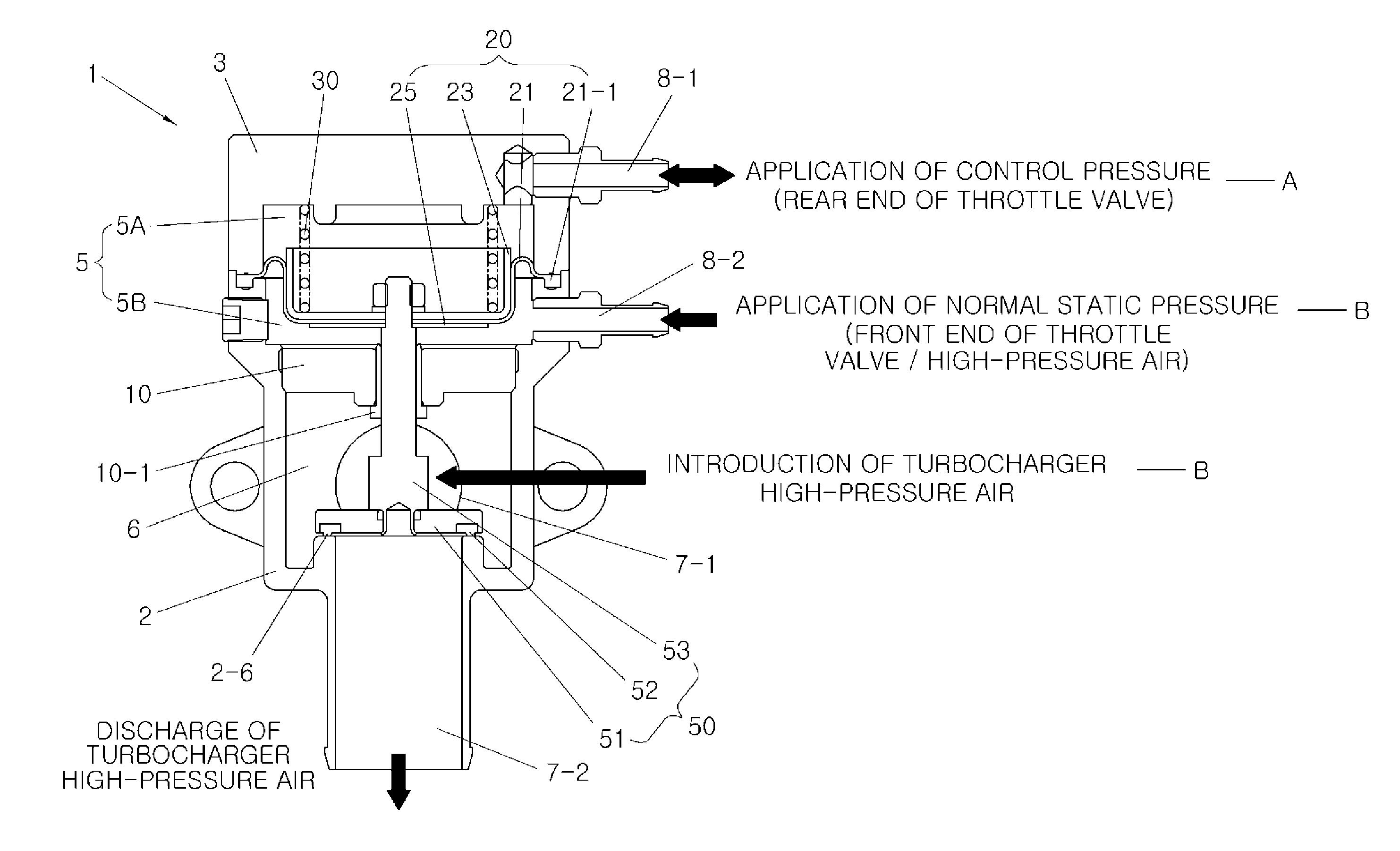
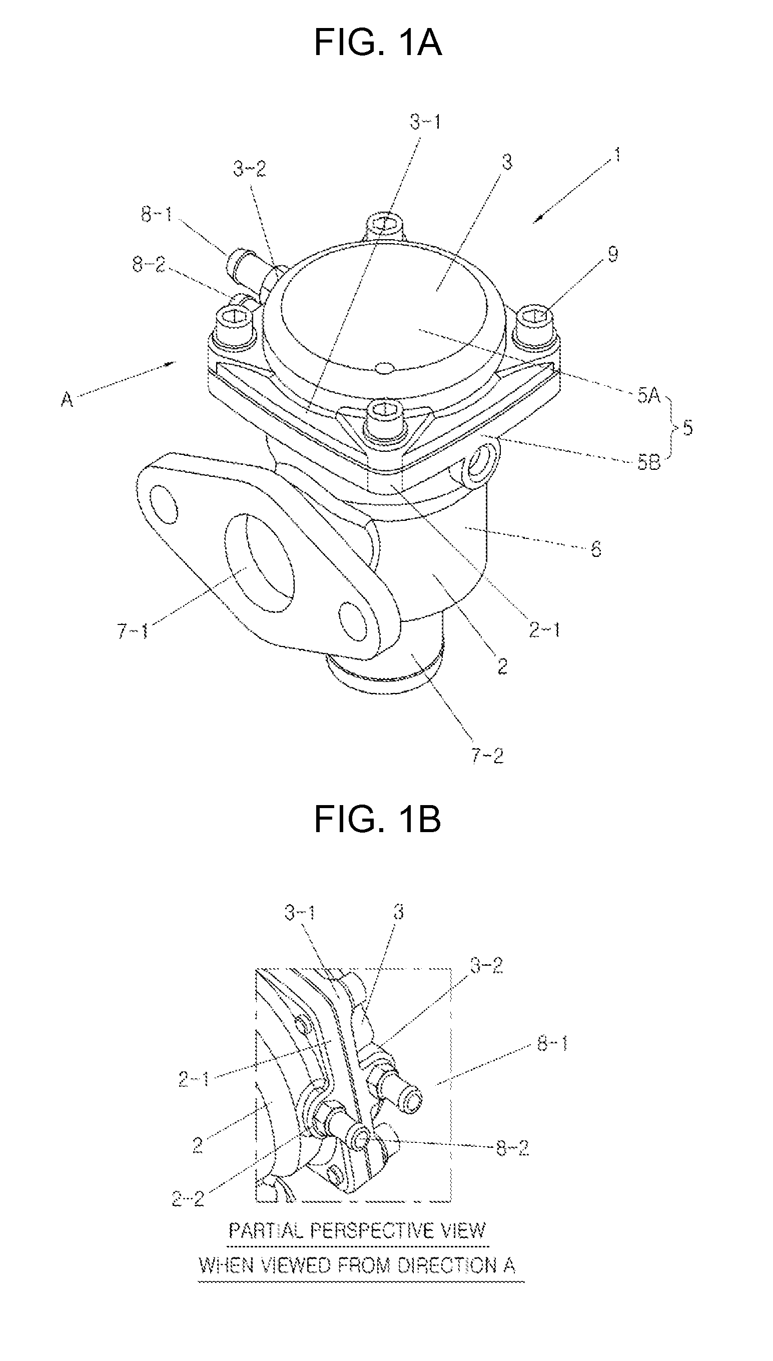
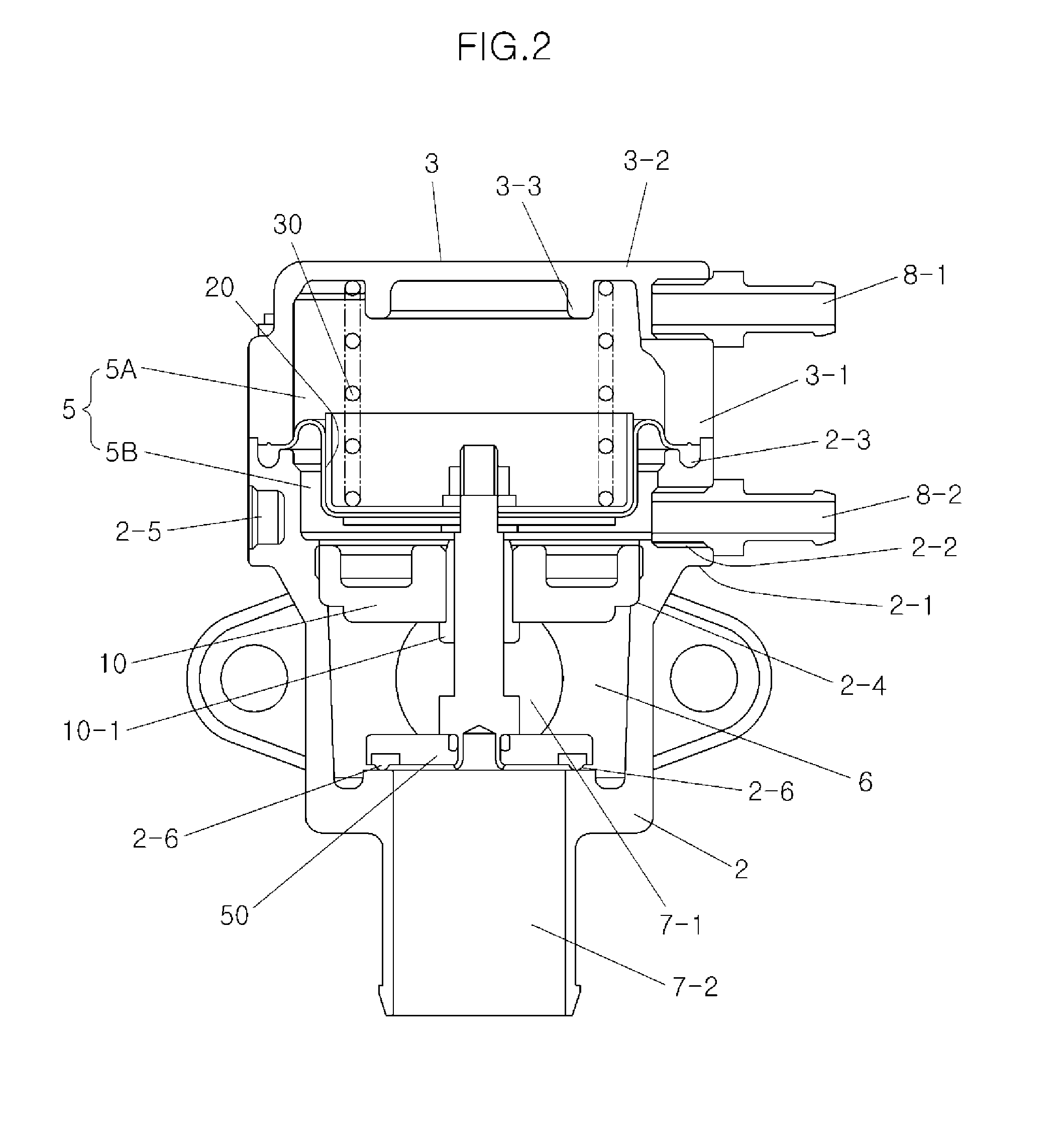
[0040]FIG. 1A and FIG. 1B are perspective views illustrating a separation chamber type anti-surge valve according to various embodiments of the present invention. FIG. 2 is a cross-sectional view of the separation chamber type anti-surge valve.

[0041]As shown in the drawings, a separation chamber type anti-surge valve 1 includes a ...


PUM


Abstract

A separation chamber type anti-surge valve may include a valve body formed with a charge air passage inlet and a charge air passage outlet, and a valve cover coupled to the valve body by a fastening member to define an empty inner space between the valve body and the valve cover, in which the inner space is divided into a diaphragm chamber and a bypass chamber by a valve guide, one side tip of a valve rod being fixed in the diaphragm chamber, a valve disc fixed to another side tip of the valve rod, and the diaphragm chamber is divided into a control pressure chamber and a normal static pressure chamber.

Description

CROSS-REFERENCE TO RELATED APPLICATIONS[0001]The present application claims priority to Korean Patent Application No. 10-2014-0050584, filed Apr. 28, 2014, the entire contents of which is incorporated herein for all purposes by this reference.BACKGROUND OF THE INVENTION[0002]1. Field of the Invention[0003]Various embodiments of the present invention relate to an anti-surge valve, and particularly, to a commercial vehicle turbocharger system in which an anti-surge valve is realized so as not to be adversely affected by high-temperature and high-pressure charge air, which is introduced thereinto, containing blow-by oil mist by means of double separation of a chamber having an increased vertical height, and to which a separation chamber type anti-surge valve is applied so that surge noise is significantly reduced and the turbocharger system is operable while securing durability.[0004]2. Description of Related Art[0005]In general, a turbocharger applied to a commercial CNG (Compressed N...

Claims


Application Information

Patent Timeline
IPC IPC(8): F02M35/10F02B43/10F02M35/104F02B29/04F02M35/16
CPCF02M35/10157F02B29/04F02M35/16F02M35/104F02B2043/103F02M35/10295F02M35/10144F02B43/10F02M35/10255F01M2011/021F02B37/16Y02T10/12
Inventor JIN, YOUNG-SOO
Owner HYUNDAI MOTOR CO LTD
Learn More