
Plug and Gun Apparatus and Method for Cementing and Perforating Casing

a gun and perforating technology, applied in the direction of sealing/packing, fluid removal, borehole/well accessories, etc., can solve the problems of insufficient data recording today to effectively measure the success or failure of a primary cement job, and not all wells that are drilled and casing strings cemented in place during the well operation, etc., to achieve the effect of increasing costs and additional drilling tim

Inactive Publication Date: 2015-10-29
WEATHERFORDLAMB
View PDF4 Cites 11 Cited by
  • Summary
  • Abstract
  • Description
  • Claims
  • Application Information

AI Technical Summary

Benefits of technology

The patent describes an assembly that allows for a reliable and effective way to establish a flow path through a well casing into a formation during a frac stages. This method can use a full size perforating gun with maximum performance charges, which provides the required hole size and penetration into the formation. Additionally, the assembly eliminates the need for changing the casing's outer diameter, which saves time and money. The guns are positioned inside the casing during the initial cementing job, resulting in a more efficient and cost-effective drilling program.

Problems solved by technology

Not all wells that are drilled and casing strings cemented in place during the well operation are problematic.
Conversely, primary cementing of problematic wells has historically been inefficient to unobtainable by manipulation of the traditional variables.
What can be recorded today to effectively measure the success or failure of a primary cement job is not adequate for cementing problematic wells.
Whether success is a leak-off test, open-hole kick-off plug, isolation of a hydrocarbon bearing zone of interest, or a fresh water zone that must be hydraulically or mechanically isolated and protected, the tools and methods that operators and service companies employ today that can be controlled and monitored are not always enough to provide the expected nor the desired results.
Coil tubing is the quicker method of running and retrieving the TCP guns, but it is also more expensive than using a workover rig.
Although creating the flow paths with tubing conveyed perforating gun is the most reliable method, it is also the most cost intensive.
In some cases, operators are unable to open the hydraulic sleeve and / or establish a high enough flow rate for pump down operations.
In this case, operators must use TCP guns to create the flow path needed at an additional cost.
As a result, reliability and a poor cement job in the lower portion of the wellbore are some disadvantages of this method.
This small size limits the performance of the shot charges and the resulting hole sizes produced in the casing.
This misalignment increases friction and can hinder flow while pumping.
Consequently, this system suffers difficulty in establishing a flow rate, getting enough flow rate for pump down operations, and in having a sufficient flow rate at reasonable pressures.
The drawbacks have proven to be substantial, as this system has high failure rates and is very time consuming to implement.
Accordingly, demand for this system is very low due to these problems.
Problems associated with this method are related to the lack of cement in the lower wellbore and potential premature breakage of the rupture discs.
Also, due to revised government regulations, this method may no longer be allowed in some places.

Method used


Image

  • Plug and Gun Apparatus and Method for Cementing and Perforating Casing
  • Plug and Gun Apparatus and Method for Cementing and Perforating Casing
  • Plug and Gun Apparatus and Method for Cementing and Perforating Casing

Examples


Embodiment Construction

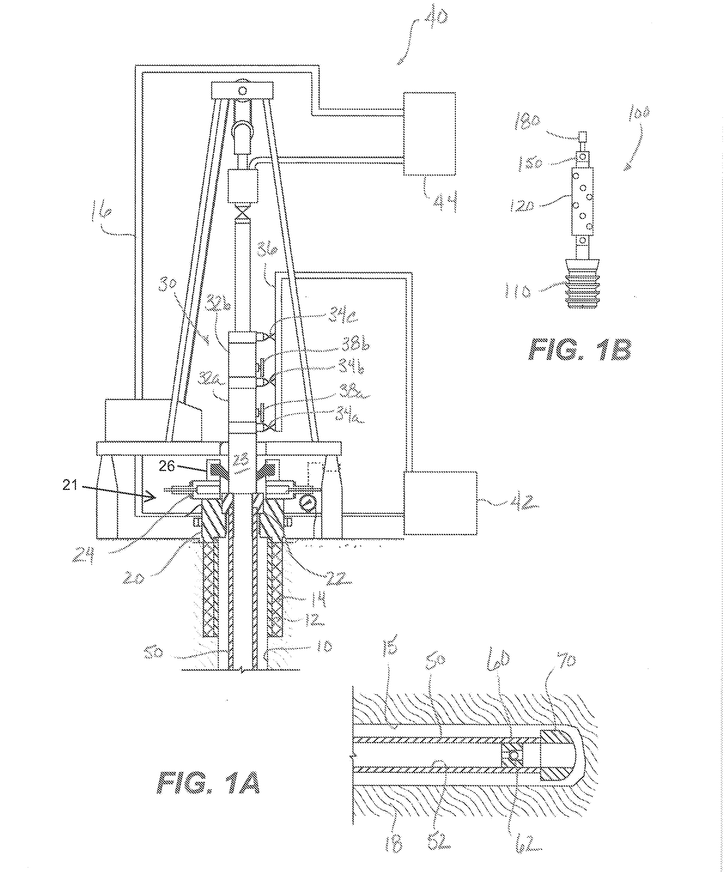
[0045]As shown in FIG. 1A, a wellhead 20 at a rig 16 is mounted on outer casing 12 deployed into a wellbore 10, and a casing adapter 23 connects a pressure control assembly 21 of the wellhead 20 to a cementing head 30. The pressure control assembly 21 typically includes a blowout preventer (BOP) 24, a rotating control device (RCD) 26, a variable choke valve, and other conventional components.

[0046]A fluid system 40 includes a cement pump 42, a mud pump 44, and other components typically used on a rig for drilling, cementing, and production operations. Various valves, spools, rotorary table, top drive, derrick, traveling block, drawworks, and other conventional components are included, but may not be discussed herein. In any event, the wellbore 10 may be a land based wellbore as shown, or it may be a subsea wellbore 10 with suitable modifications to the wellhead 20 and other components.

[0047]The cementing head 30 includes launchers 32a-b and a manifold 36 having trunks, branches, shu...


PUM


Abstract

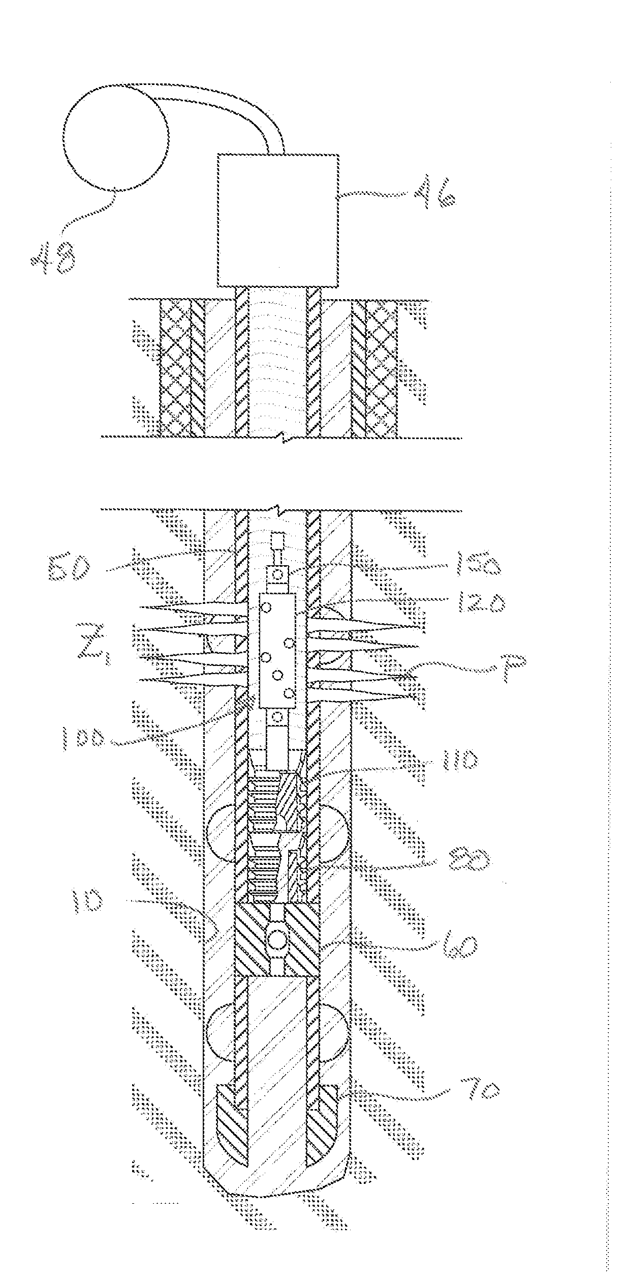
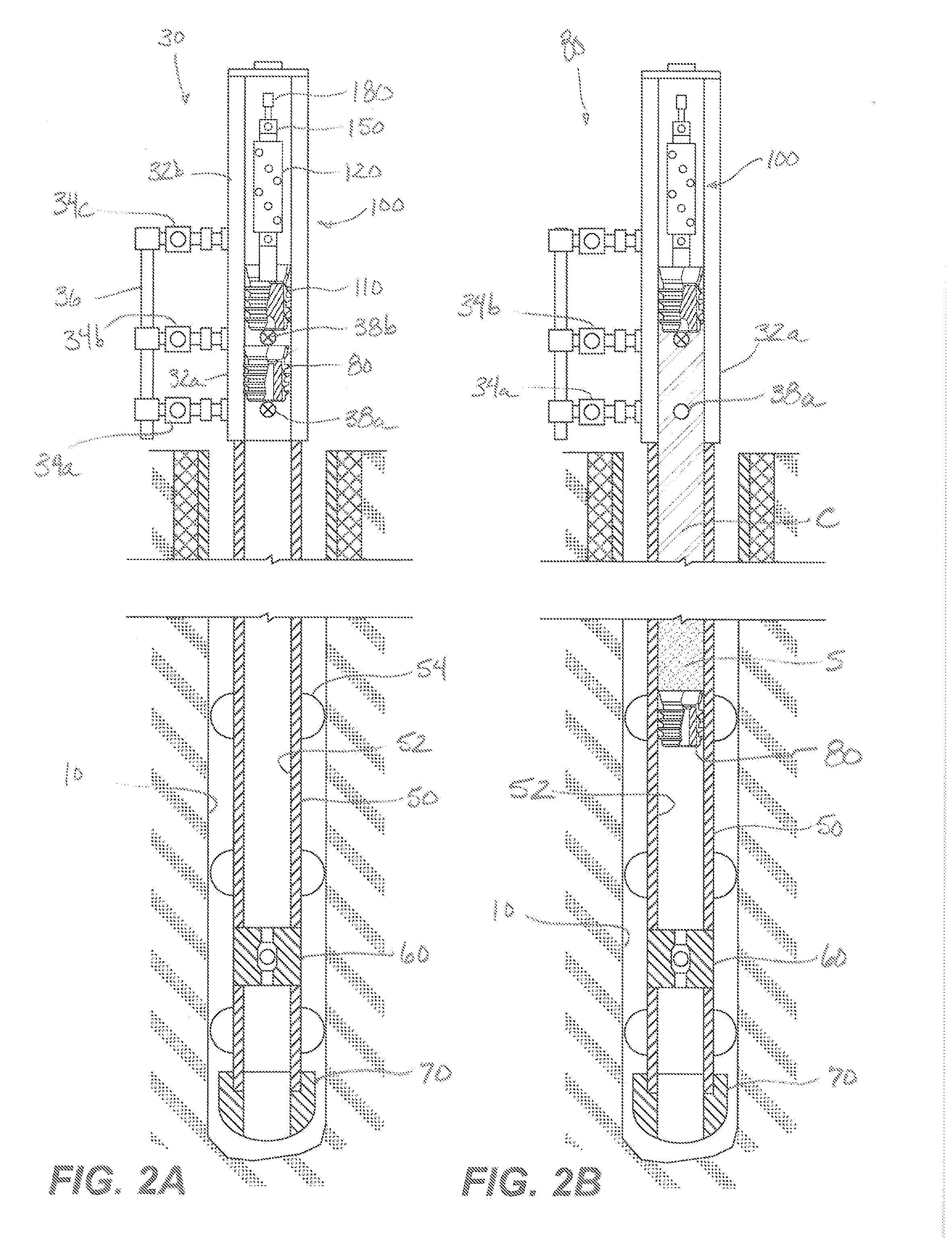
An apparatus is used in cementing and perforating casing in a borehole. A cement head disposed on the casing has first and second containers. A first plug positioned in the first container deploys from the cement head in the casing in advance of cement slurry. An assembly positioned in the second container deploys from the cement head in the casing after the cement slurry. The first plug lands on a float collar on the casing, and a breachable passage in the first plug opens and allows the cement slurry to pass into the borehole annulus. The assembly has a wiper and has one or more charges. The wiper wipes the casing as the assembly is displaced down the casing with displacing fluid. Eventually, the assembly lands at the first plug, and hydraulic pressure applied in the casing activates the one or more charges to perforate the casing.

Description

BACKGROUND OF THE DISCLOSURE[0001]Deviated or horizontal wells drilled in a formation typically have a casing cemented in the borehole. The casing and surrounding cement are perforated with holes to provide communication between the casing and the surrounding formation. Using such perforations, operators can perform any number of operations, such as hydraulic fracturing or dispensing acid or other chemicals into the producing formation. Additionally, the perforations can be used for production flow into a producing string disposed in the casing during producing operations.[0002]In wellbore construction and completion operations, a wellbore is formed to access hydrocarbon-bearing formations (e.g., crude oil and / or natural gas) by the use of drilling. Drilling is accomplished by utilizing a drill bit that is mounted on the end of a drill string. To drill within the wellbore to a predetermined depth, the drill string is often rotated by a top drive or rotary table on a surface platform...

Claims


Application Information

Patent Timeline
Patent Type & Authority Applications(United States)
IPC IPC(8): E21B29/08
CPCE21B29/08E21B33/16E21B43/11852
Inventor CAPPS, GAYLEN O.DE LA CRUZ, DAVIDKLATT, DUDLEYSQUYRES, BYRON S.
Owner WEATHERFORDLAMB
Learn More