Buckle for Connector, and Method for Assembling Same

Active Publication Date: 2015-10-22
SANOH IND CO LTD
View PDF0 Cites 3 Cited by
  • Summary
  • Abstract
  • Description
  • Claims
  • Application Information

AI Technical Summary

Benefits of technology

The invention provides a buckle for a connector that has a small and simple structure, is easily productive, and can be easily assembled. This solves the various problems of the conventional art.

Problems solved by technology

Connector buckles are required to have a smaller and simpler structure, because connector buckles are obstacles against utilization of the space inside the vehicles.
Particularly, in the back seat, a large connector buckle would touch the waist of a passenger and give an uncomfortable feeling.
In a type of a vehicle in which the seat belt device can be retracted inside the vehicle when nobody is sitting, a connector buckle left on the seat would become an obstacle against space utilization such as mounting of baggage on the seat, etc.
However, in the base member 110 formed in this way, the inner region 111 cannot have a height shorter than the thickness of the sheet metal, which leads to a problem that the base member 110 cannot avoid being thick.
However, mechanical strength of a thin sheet metal is low, and the sheet metal may be torn during working.
It is difficult to perform such diagonal assembly mechanically, which is a cause of reducing the productivity of the connector buckle 100.
Hence, in the current circumstances, there is no satisfactory connector buckle available that has a small and simple structure and has a favorable productivity.

Method used


Image

  • Buckle for Connector, and Method for Assembling Same
  • Buckle for Connector, and Method for Assembling Same
  • Buckle for Connector, and Method for Assembling Same

Examples


Embodiment Construction

[0068]A buckle for a connector according to one embodiment of the present invention will be described in detail with reference to the drawings.

[0069]FIG. 2A is a plan view of a buckle for a connector according to one embodiment of the present invention. FIG. 2B is a side elevation thereof. FIG. 2C is a plan view of the buckle for a connector in a state of being engaged with a tongue. FIG. 2D is a side elevation thereof.

[0070]As shown in these drawings, the buckle for a connector 1 is constructed such that the buckle structure thereof is housed in a cover member composed of an upper cover 60a and a lower cover 60b, and is engageable with and disengageable from a tongue 101. The upper cover 60a and the lower cover 60b have ring portions 61a and 61b in which a webbing extended from an arbitrary vehicle member is hooked to be passed around.

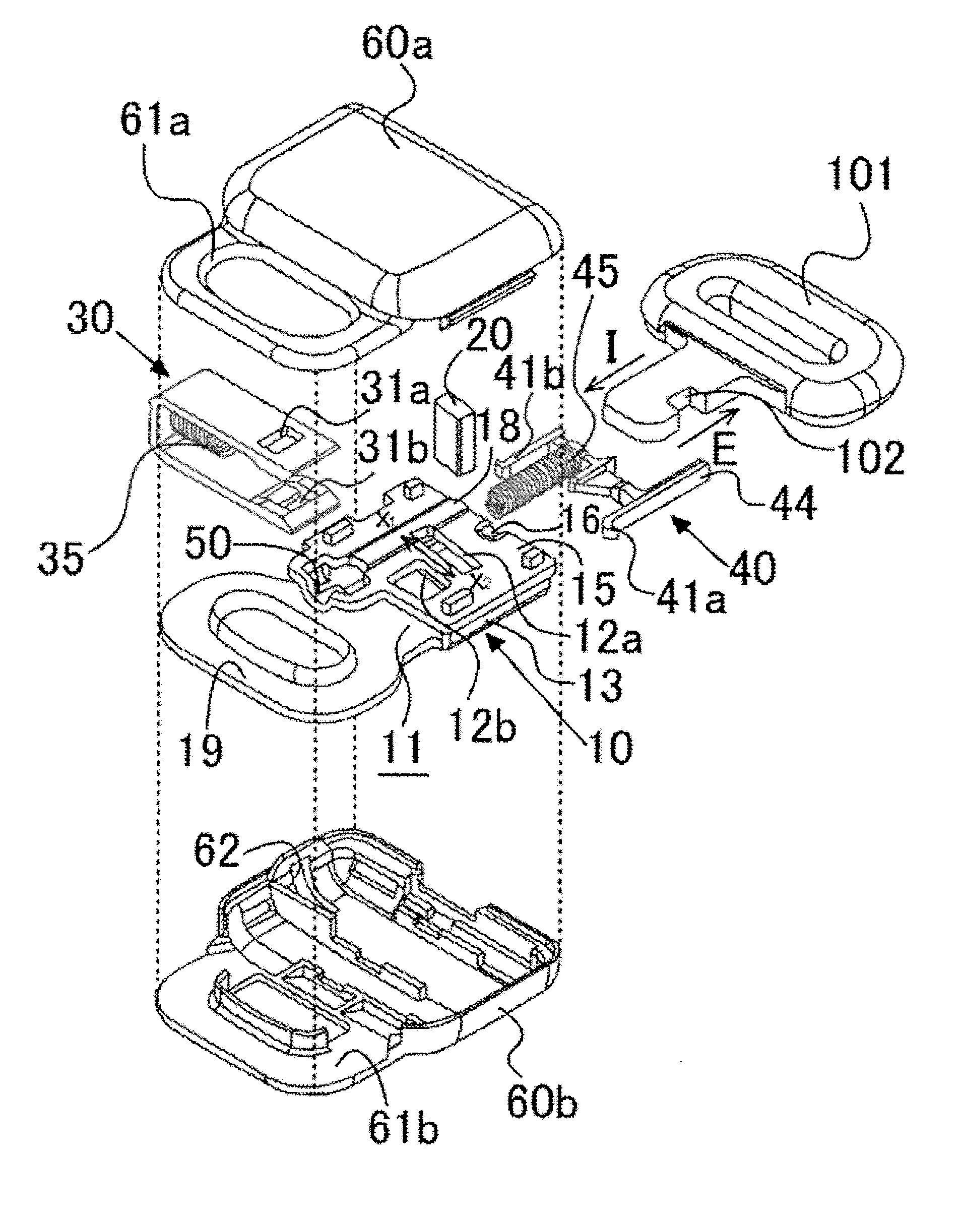
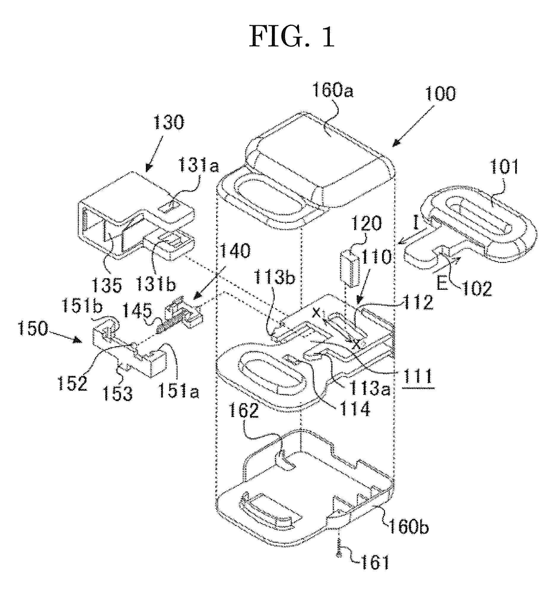
[0071]The buckle structure of the buckle for a connector 1 will be described with reference to FIG. 3. FIG. 3 is an exploded perspective diagram of a...


PUM


Abstract

[Problem] To provide a buckle for a connector having a small simple structure and a favorable productivity, and a method for assembling the same.[Solution] A buckle for connector 1 of the present invention for supporting a tongue 101 engageably / disengageably includes a base member 10, a latch member 20, an unlocking member 30, a latch spring 35, an ejector 40, an ejector spring 45, and cover members 60a, 60b housing these members. The base member 10 includes first and second plates 13, 15. The ejector 40 includes: two arms 41a, 41b; a body section between the arms 41a, 41b that includes a pushing / moving surface for the tongue 101 to be pushed / moved by the tongue 101, a support section to support the latch member 20, and a pushing surface to be pushed by the ejector spring 45; and claws formed at ends of the arms 41a,41b and locked with an aperture at a terminal end of the base member 10, the terminal end being opposite to a starting end from which the tongue 101 is inserted.

Description

TECHNICAL FIELD [0001]The present invention relates to a buckle for a connector used in conjunction with a seat belt of a vehicle, and a method for assembling the same.BACKGROUND ART [0002]With a three-point seat belt, a passenger constrains his / her body by pulling a seat belt tongue held at his / her shoulder to withdraw a shoulder belt and waist belt formed of one webbing simultaneously, and inserting the seat belt tongue into a seat belt buckle provided at a seat portion opposite to the position from where the waist belt is withdrawn in a manner to constrain the upper body and waist of the passenger.[0003]The structure from which the waist belt is withdrawn is classified into a structure configured to fix one end of the waist belt to the seat or a surrounding member directly, and a structure configured to fix one end of the waist belt engageably and disengageably to the seat or a surrounding member via a buckle. The buckle in the latter structure is called a connector buckle, and u...

Claims


Application Information

Patent Timeline
IPC IPC(8): A44B11/25B60R22/12
CPCA44B11/2511B60R22/12A44B11/2561A44B11/2534A44B11/2515
Inventor HA, HUY HUNGKAWAI, YOSHIHIKO
Owner SANOH IND CO LTD
Why Eureka
Try Eureka