
Sensing apparatus

a sensor and circuit technology, applied in the field of sensor circuit methods, can solve the problems of short lifespan, mechanical movement is not delivered, and the amplitude of a driving signal inputted to the sensor apparatus needs to be greatly increased, so as to reduce the influence of noise and high snr value

Inactive Publication Date: 2015-10-15
POSTECH ACAD IND FOUND
View PDF9 Cites 19 Cited by
  • Summary
  • Abstract
  • Description
  • Claims
  • Application Information

AI Technical Summary

Benefits of technology

The present invention aims to solve problems in existing sensing apparatuses by providing a sensing apparatus that maintains a high signal-to-noise ratio (SNR) level while keeping the amplitude of the input signal low. This is achieved by reducing the impact of noise from the sensor element while maintaining a small input signal amplitude. The invention is particularly useful for capacitive touch sensors, where the input signal amplitude remains low and can reliably detect the presence and touch position regardless of noise from the display.

Problems solved by technology

However, the amplitude of a driving signal inputted to the sensor apparatus needs to be greatly increased in order to obtain a sufficient SNR because noise components induced from the sensor apparatus also appear in the output signal of a sensor circuit.
However, the initial touch sensor panels are disadvantageous in that they have a short lifespan because a mechanical movement must be transferred for touch sensing.
Although a finger or a pen touches the tempered glass, a mechanical movement is not delivered to the glass plane for the touch sensor panel placed under the tempered glass and a flat panel display device.
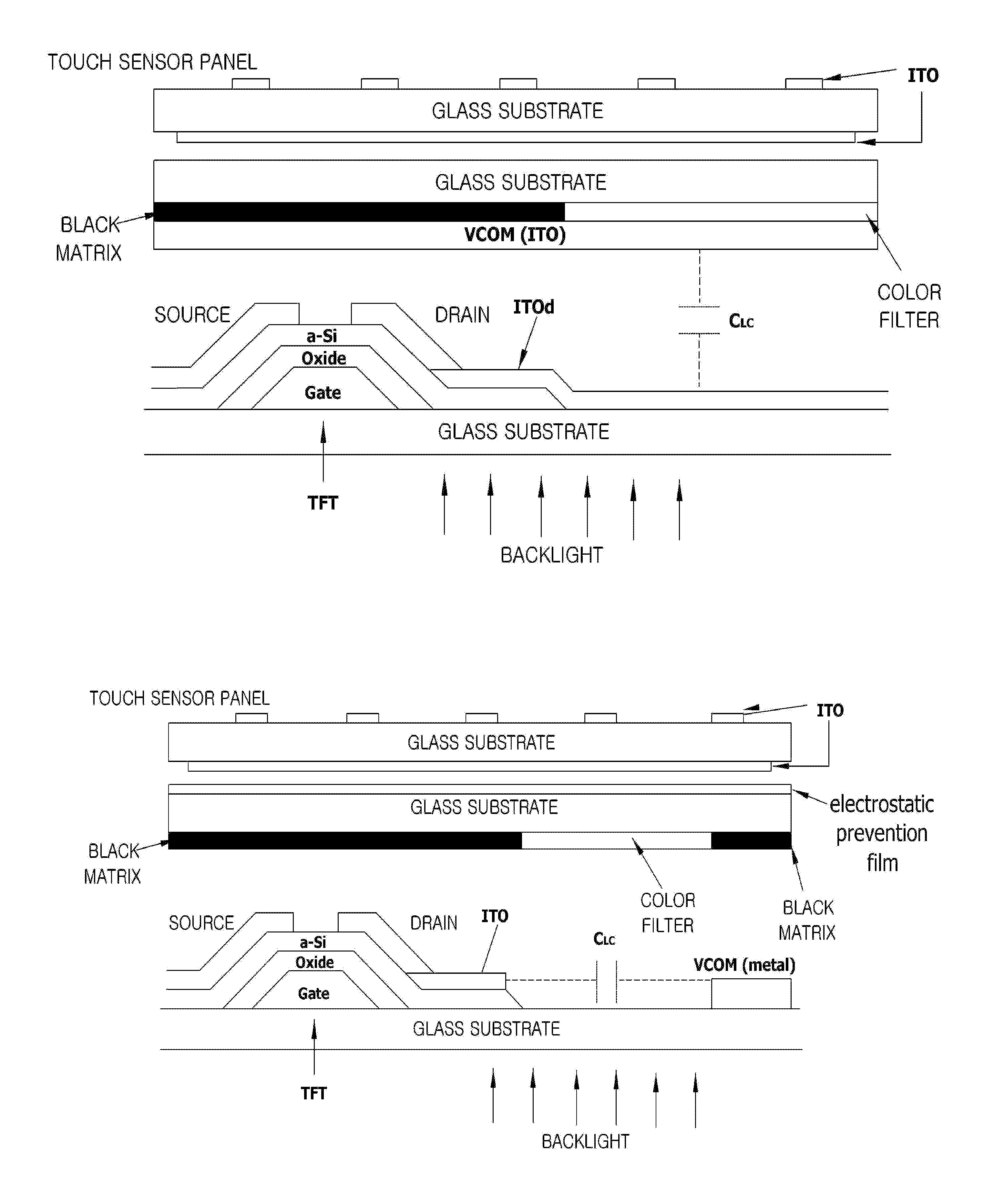
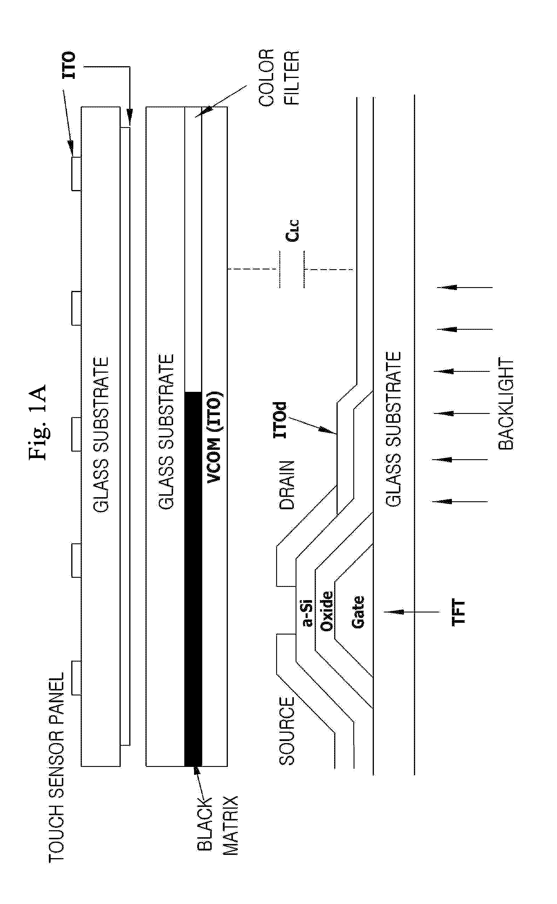
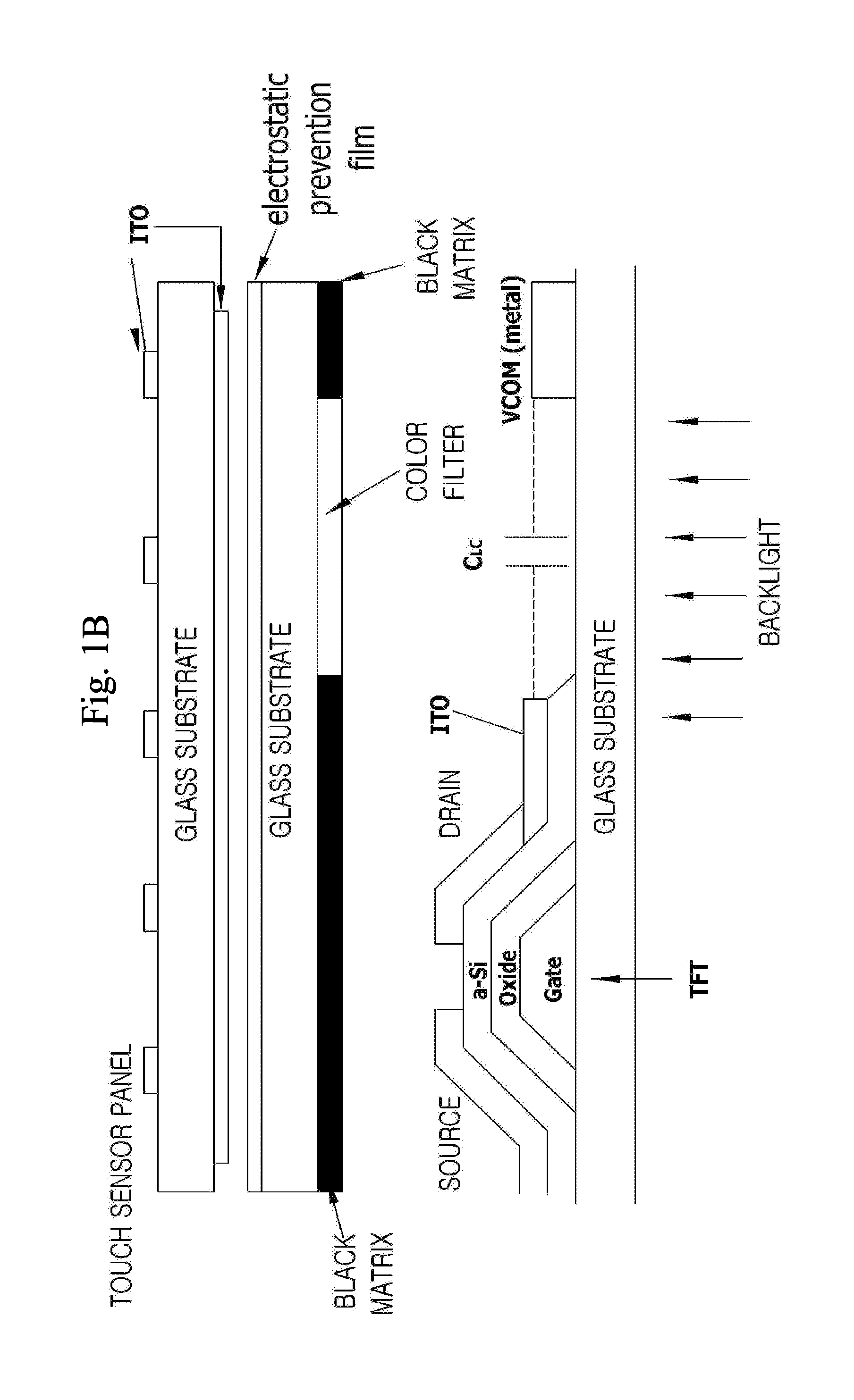
In the capacitive touch method of measuring mutual capacitance, however, an SNR is very small due to common electrode (VCOM) noise which is generated from a flat panel display, such as an LCD or OLEDs.

Method used


Image

  • Sensing apparatus
  • Sensing apparatus
  • Sensing apparatus

Examples


Embodiment Construction

[0053]Reference will now be made in greater detail to a preferred embodiment of the invention, an example of which is illustrated in the accompanying drawings. Wherever possible, the same reference numerals will be used throughout the drawings and the description to refer to the same or like parts.

[0054]Hereinafter, detailed embodiments of the present invention are described in detail with reference to the accompanying drawings. Each of elements or characteristics may be considered to be optional unless otherwise described explicitly. Each element or characteristic may be implemented in such a way as not to be combined with other elements or characteristics. Furthermore, some of the elements and / or the characteristics may be combined to form an embodiment of the present invention. Order of operations described in the embodiments of the present invention may be changed. Some of the elements or characteristics of an embodiment may be included in another embodiment or may be replaced w...


PUM


Abstract

The present invention relates to a sensor circuit method for securing a sufficient Signal to Noise Ratio (SNR) by reducing the influence of noise induced from a sensor element which appears in the final output signal of a reception unit although an input signal having a relatively small amplitude is used in a sensing apparatus in which a time-periodic signal having a relatively higher frequency as compared with the speed of change of a behavior of a user or a movement of an object to be sensed, such as a capacitive sensor or an inductive sensor, is used as an input signal. Power consumption of a touch sensor chip can be reduced even without increasing the amplitude of a touch sensor panel driving signal, and a production cost for a touch sensor chip can be reduced by removing a high voltage driver.

Description

BACKGROUND OF THE INVENTION[0001]1. Field of the Invention[0002]The present invention relates to a sensor circuit method for securing a sufficient Signal to Noise Ratio (SNR) by reducing the influence of noise induced from a sensor element which appears in the final output signal of a reception unit although an input signal having a relatively small amplitude is used in a sensing apparatus in which a time-periodic signal having a relatively higher frequency as compared with the speed of change of a behavior of a user or a movement of an object to be sensed, such as a capacitive sensor or an inductive sensor, is used as an input signal. More particularly, in order to illustrate embodiments of the present invention, the contents of the present invention have been applied to a touch sensor which is used in flat panel displays, such as a Liquid Crystal Display (hereinafter referred to as an ‘LCD’) and Organic Light-Emitting Diodes (hereinafter referred to as an ‘OLED’). The present inve...

Claims


Application Information

Patent Timeline
Patent Type & Authority Applications(United States)
IPC IPC(8): G06F3/041G06F3/044
CPCG06F3/044G06F3/0412G06F3/04182G06F3/0446G06F3/0418G09G3/3648
Inventor PARK, HONG JUNELEE, SANG SUYEO, DONG HEELEE, JAE SEUNG
Owner POSTECH ACAD IND FOUND
Learn More