
Strain engineering in back end of the line

a technology of strain engineering and back end, applied in the field of strain-based performance enhancement of semiconductor devices, can solve the problems that metal oxide semiconductor transistors are beginning to reach their traditional scaling limits

Active Publication Date: 2015-10-08
IBM CORP
View PDF16 Cites 14 Cited by
  • Summary
  • Abstract
  • Description
  • Claims
  • Application Information

AI Technical Summary

Benefits of technology

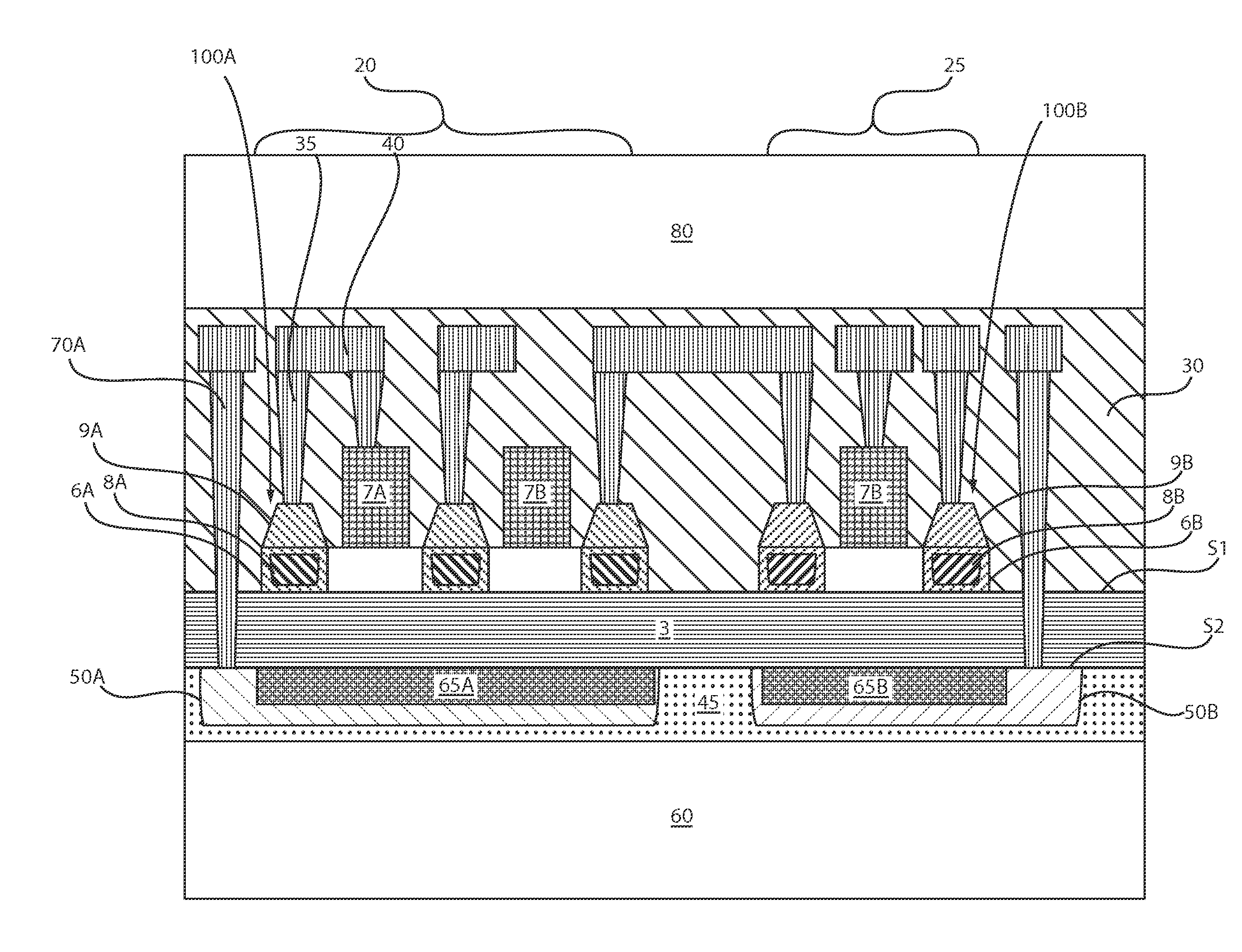
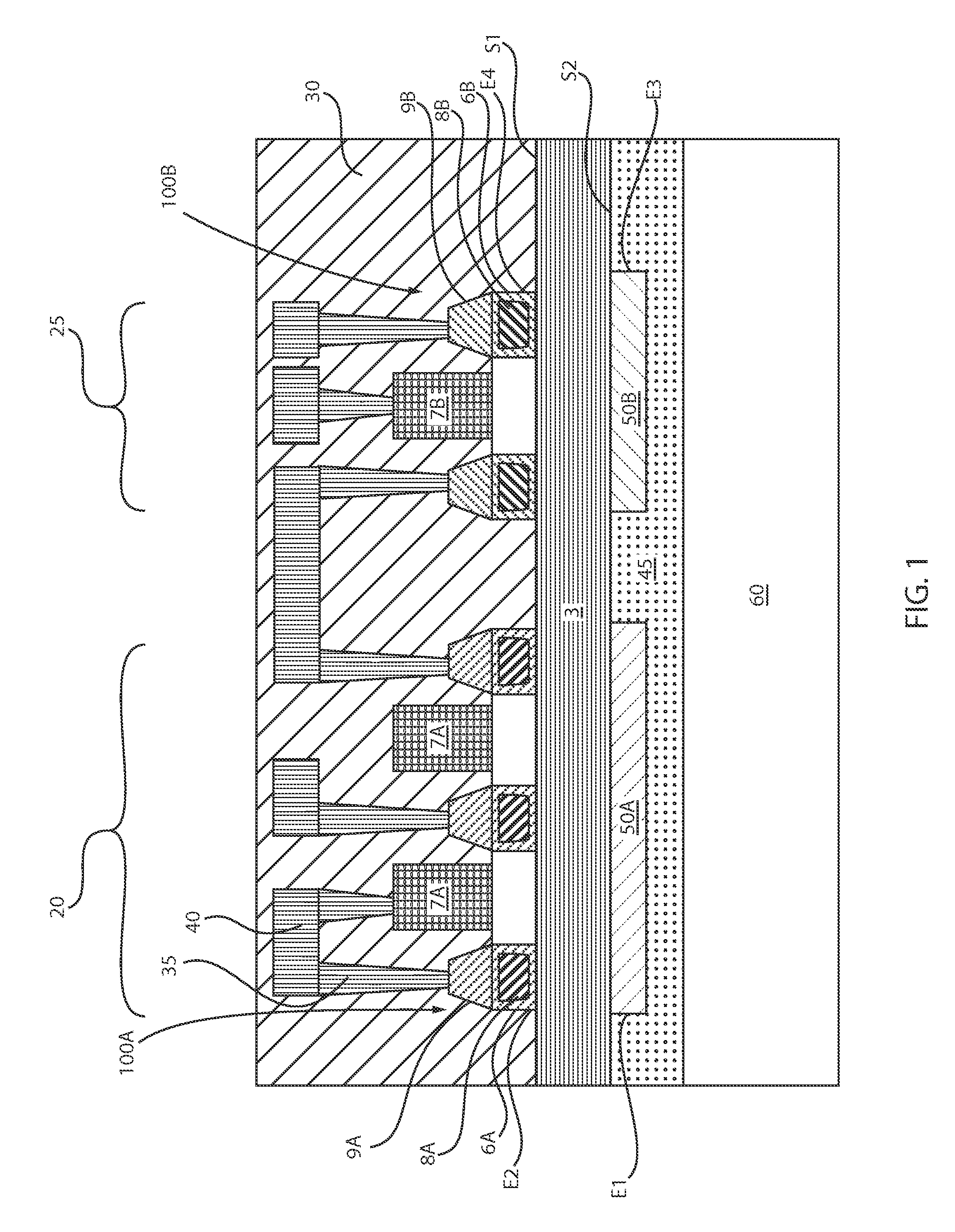
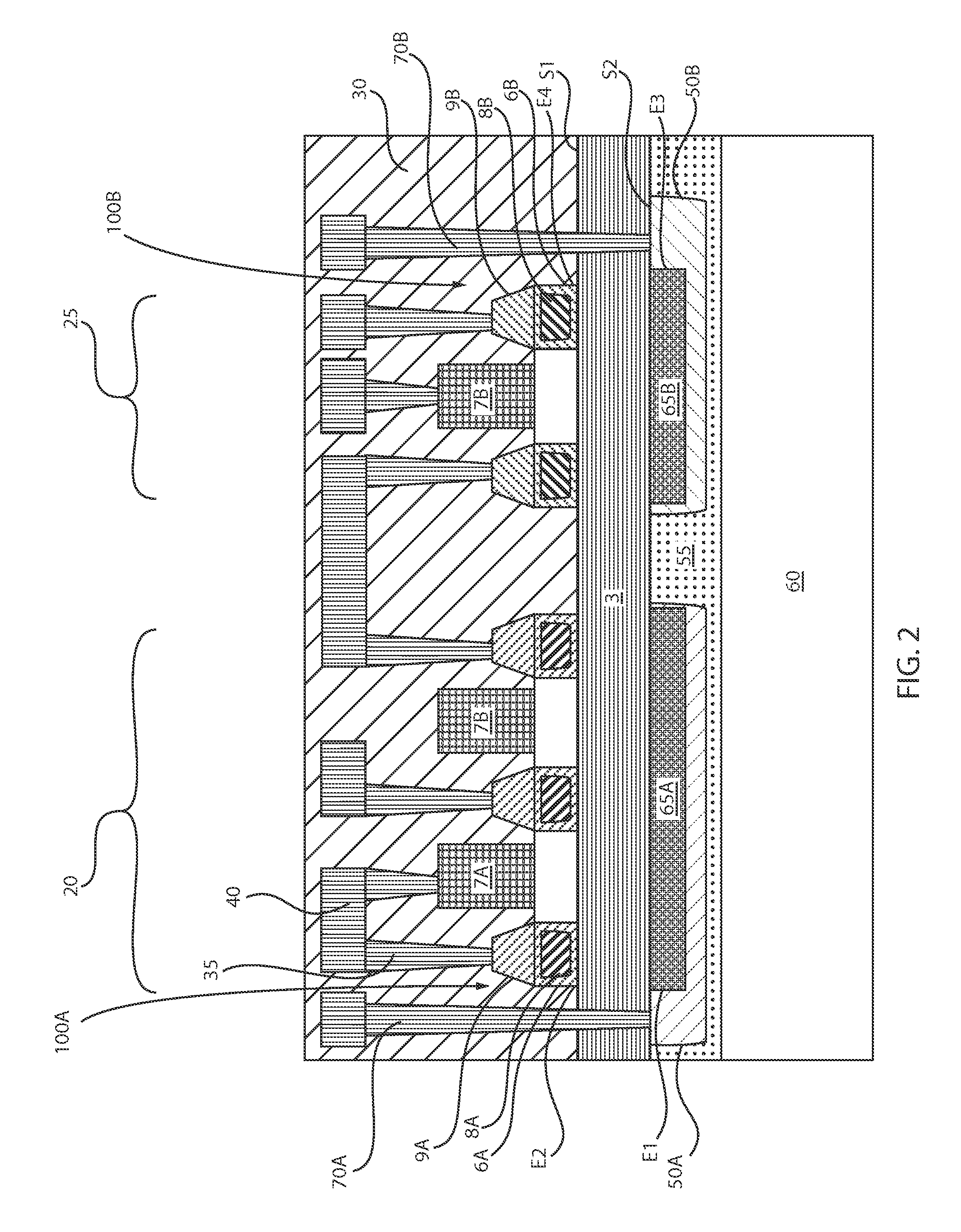
The patent text describes a semiconductor device that includes a stressor structure on one side of a dielectric layer and a semiconductor device on the other side of the layer. The stressor structure induces a stress that affects the operation of the semiconductor device. The text also describes a method of making this device. The technical effect of this patent is to improve the performance and reliability of semiconductor devices in electronic devices that operate under stress conditions.

Problems solved by technology

However, there are growing signs today that metal oxide semiconductor transistors are beginning to reach their traditional scaling limits.

Method used


Image

  • Strain engineering in back end of the line
  • Strain engineering in back end of the line
  • Strain engineering in back end of the line

Examples


Embodiment Construction

[0020]Detailed embodiments of the claimed structures and methods are disclosed herein; however, it is to be understood that the disclosed embodiments are merely illustrative of the claimed structures and methods that may be embodied in various forms. In addition, each of the examples given in connection with the various embodiments are intended to be illustrative, and not restrictive. Further, the figures are not necessarily to scale, some features may be exaggerated to show details of particular components. Therefore, specific structural and functional details disclosed herein are not to be interpreted as limiting, but merely as a representative basis for teaching one skilled in the art to variously employ the methods and structures of the present disclosure. For purposes of the description hereinafter, the terms “upper”, “lower”, “right”, “left”, “vertical”, “horizontal”, “top”, “bottom”, and derivatives thereof shall relate to the embodiments of the disclosure, as it is oriented ...


PUM


Abstract

A semiconductor device including at least one semiconductor device on a first surface of a dielectric layer, and at least one stressor structure having an intrinsic stress on a second surface of the dielectric layer. The at least one semiconductor device and the at least one stressor structure are present on opposing sides of the dielectric layer. The at least one stressor structure induces a stress on the at least one semiconductor device opposite the intrinsic stress.

Description

BACKGROUND[0001]1. Technical Field[0002]The present invention relates to semiconductor devices, and more particularly to strain based performance enhancements in semiconductor devices.[0003]2. Description of the Related Art[0004]For more than three decades, the continued miniaturization of silicon metal oxide semiconductor field effect transistors (MOSFETs) has driven the worldwide semiconductor industry. Various showstoppers to continued scaling have been predicated for decades, but a history of innovation has sustained Moore's Law in spite of many challenges. However, there are growing signs today that metal oxide semiconductor transistors are beginning to reach their traditional scaling limits. Since it has become increasingly difficult to improve MOSFET performance and consequently the overall performance of the complementary metal oxide semiconductor (CMOS) circuits through continued scaling, methods for improving performance without scaling have become critical. One method for...

Claims


Application Information

Patent Timeline
IPC IPC(8): H01L27/12H01L21/768H01L21/8238H01L29/78H01L27/092H01L21/84
CPCH01L27/1203H01L27/0922H01L21/84H01L21/823807H01L29/7845H01L29/7843H01L21/76877H01L21/6835H01L2221/68327H01L2221/68381H01L29/78603H01L29/78618H01L29/78654H01L21/743H01L29/7848H01L29/7849H01L21/7624
Inventor BEDELL, STEPHEN W.HAENSCH, WILFRIED E.HEKMATSHOARTABARI, BAHMANSHAHIDI, GHAVAM G.SHAHRJERDI, DAVOOD
Owner IBM CORP
Learn More