Three-Dimensional Molding Equipment and Manufacturing Method For Three-Dimensional Shape Plastic Object

a three-dimensional shape, molding equipment technology, applied in the direction of additive manufacturing processes, manufacturing tools, electric/magnetic/electromagnetic heating, etc., can solve the problems of plastic object shape deformation such as warpage, uneven temperature distribution in the entire plastic object, etc., to reduce the deflection of temperature distribution in a region, improve molding efficiency, and avoid the effect of shape deformation

Inactive Publication Date: 2015-10-08
MATSUURA MACHINERY
View PDF11 Cites 9 Cited by
  • Summary
  • Abstract
  • Description
  • Claims
  • Application Information

AI Technical Summary

Benefits of technology

[0011]According to the present invention based on the above basic configuration, molding efficiency is improved by radiating the light beam or electron beam in the continuous route, and also occurrence of s...

Problems solved by technology

As a result, due to the above temperature difference, temperature distribution in an entire plastic object may...

Method used


Image

  • Three-Dimensional Molding Equipment and Manufacturing Method For Three-Dimensional Shape Plastic Object
  • Three-Dimensional Molding Equipment and Manufacturing Method For Three-Dimensional Shape Plastic Object
  • Three-Dimensional Molding Equipment and Manufacturing Method For Three-Dimensional Shape Plastic Object

Examples


example 1

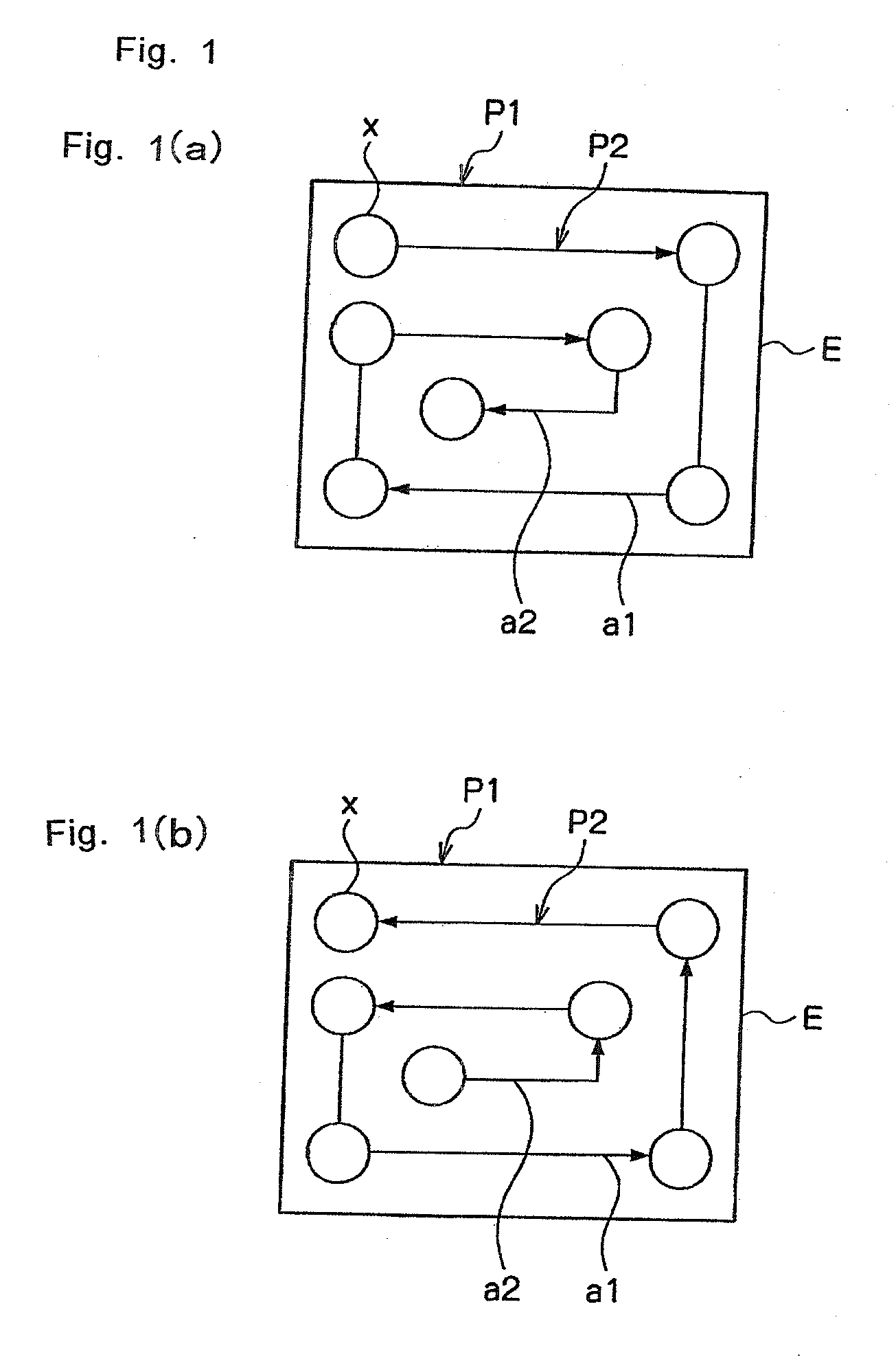
[0037]As is illustrated in FIGS. 1(a) and 1(b), according to example 1, the molding path is in an arrangement state in which a plurality of straight lines is connected at a predetermined angle and sequentially directed to the inside or sequentially directed to the outside, or in an arrangement state where a single continuous curve line is sequentially directed to the inside or sequentially directed to the outside.

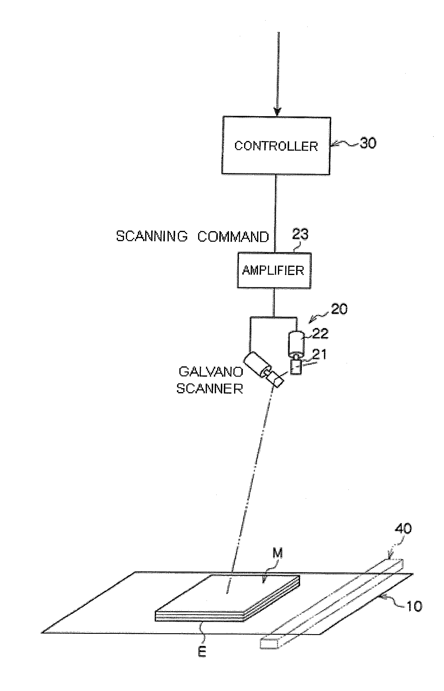
[0038]Explaining concretely the state of achieving the arrangement state more in detail, as illustrated in FIG. 3, the controller 30 actuates the powder supply equipment 40 based on the preliminarily stored processing program, and forms the powder layer on the molding table 10. Subsequently, the controller 30 actuates the light beam or electron beam scanning unit 20 to radiate the light beam or electron beam to the upper surface of the powder layer.

[0039]More specifically, the controller 30 sets a region to be molded E on the molding table 10 based on the three-dimensional ...

example 2

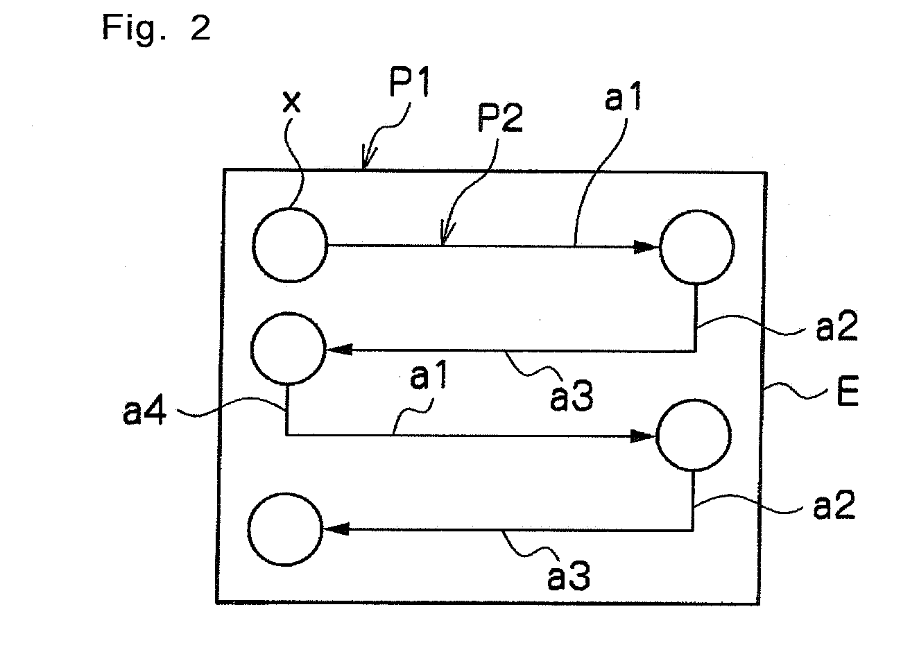
[0055]As is illustrated in FIG. 2, according to example 2, the molding path includes a scanning pattern formed of: a first scanning route directed from one side to the other side; a second scanning route continued from the first scanning route and directed in a direction away from the first scanning route at a predetermined angle with respect to the first scanning route; a third scanning route continued from the second scanning route and directed from the other direction to the one direction at a predetermined angle with respect to the second scanning route; and a fourth scanning route continued from the third scanning route and directed in a direction away from the third scanning route at a predetermined angle with respect to the third scanning route, and further this scanning pattern can be repeatedly arranged.

[0056]Explaining concretely the situation of forming the molding path more in detail, a raster molding path P2 includes: a scanning pattern formed of a first scanning route ...


PUM

PropertyMeasurementUnit
Angleaaaaaaaaaa
Diameteraaaaaaaaaa

Abstract

Three-dimensional molding equipment includes powder supply equipment which forms powder layer in a laminating process; and a beam scanning unit which radiates a light or electron beam to the powder layer and moves a radiated location of the beam to sinter the powder layer, wherein the laminating and sintering processes alternately repeat, a molding path to be a scanning route of the beam on the inside of an object to be molded is preliminarily set as a continuous route which does not pass a same line and does not form any intersection, and the beam is continuously radiated along the molding path, wherein two molding paths adjacent each other formed of two straight or curve lines are set, and a distance between the adjacent scanning routes is formed larger than a radiation diameter of the beam and not larger than ten-times the radiation diameter of the same.

Description

BACKGROUND OF THE INVENTION[0001]The present invention relates to three-dimensional molding equipment and a manufacturing method for a three-dimensional shape object, in which the three-dimensional shape plastic object is manufactured by laminating and sintering powder material.PRIOR ARTS[0002]According to this kind of invention in prior arts, a three-dimensional shape plastic object including a number of sintered layers is manufactured by repeating a process of supplying powder material from powder supply equipment to form a powder layer and a process of radiating a light beam or an electron beam to a predetermined region of the powder layer formed in the mentioned process to sinter the powder in the predetermined region.[0003]Meanwhile, according to the above prior arts, a galvano scanner device is used to radiate the light beam or electron beam in most cases. For example, Patent Document 1 (JP 2005-336547 A) discloses an invention in which a light beam or an electron beam emitted...

Claims


Application Information

Patent Timeline
IPC IPC(8): B29C67/00
CPCB29C67/0088B29C67/0077B33Y50/02B33Y10/00B33Y30/00B29K2105/251B29C64/153B29C64/393Y02P10/25
Inventor MAEDA, TOSHIOISHIMOTO, KOUSUKETAKEZAWA, YASUNORIKATO, TOSHIHIKOAMAYA, KOICHI
Owner MATSUURA MACHINERY
Why Eureka
Try Eureka