Scintillator material
- Summary
- Abstract
- Description
- Claims
- Application Information
AI Technical Summary
Benefits of technology
Problems solved by technology
Method used
Image

Examples
first embodiment
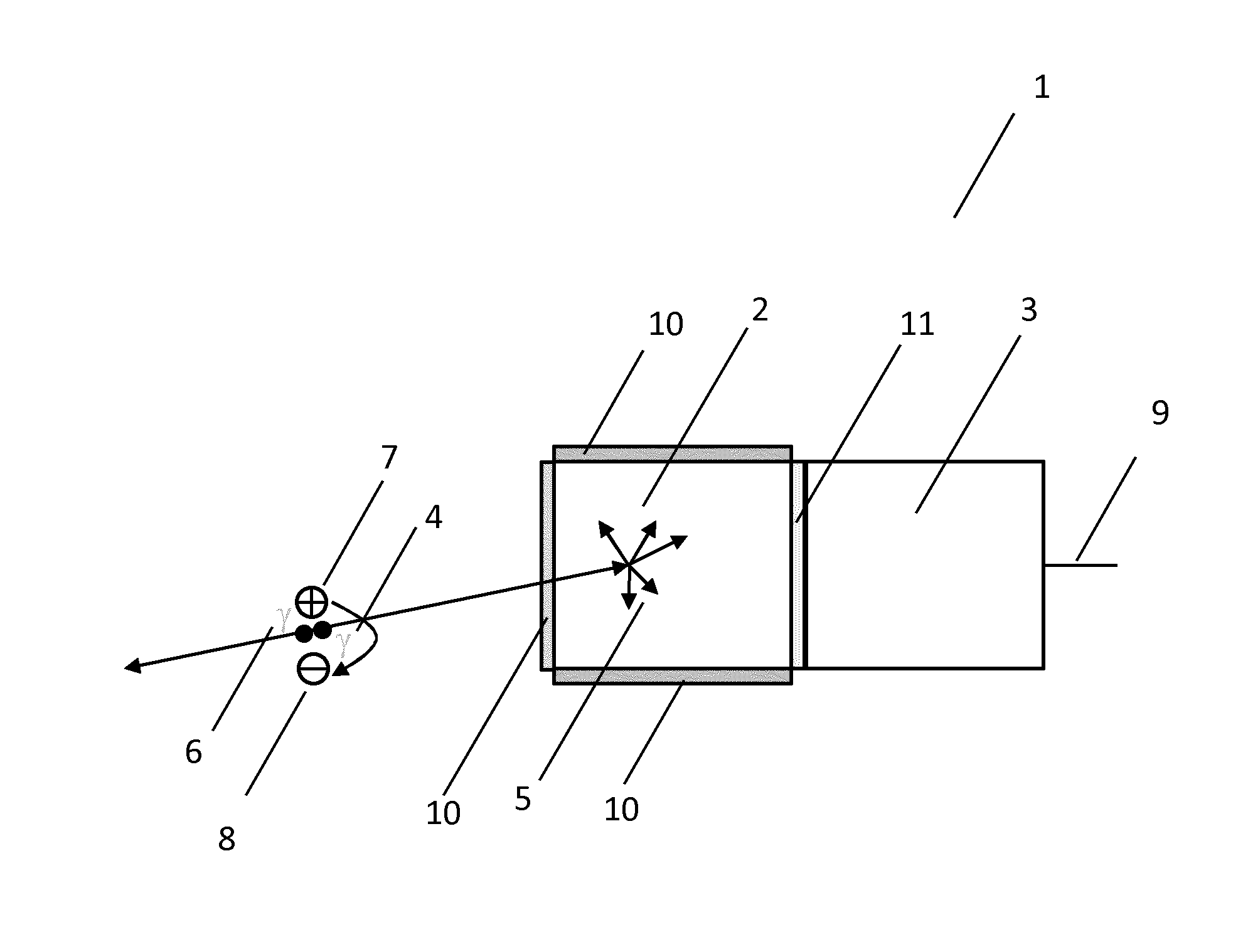
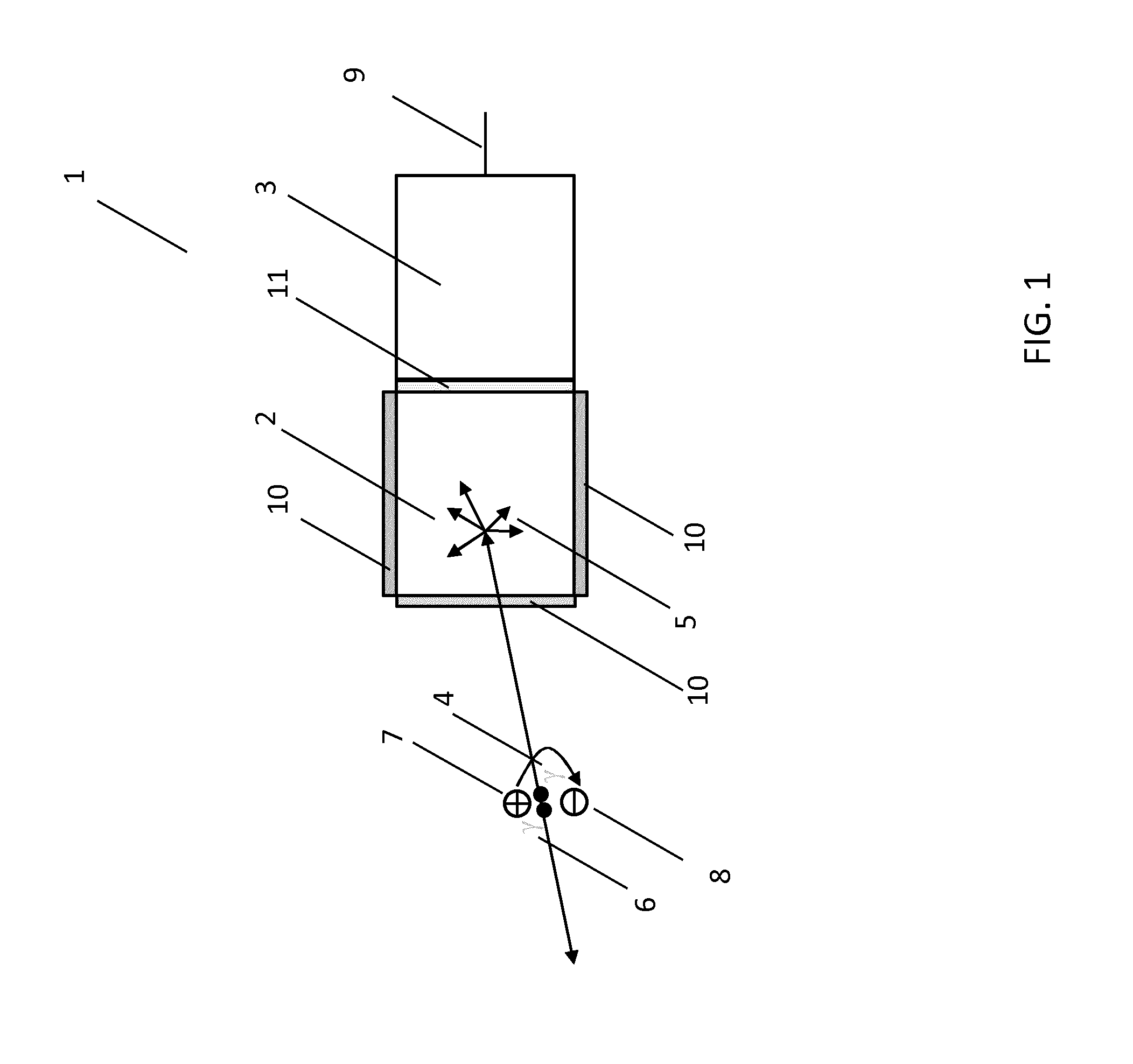
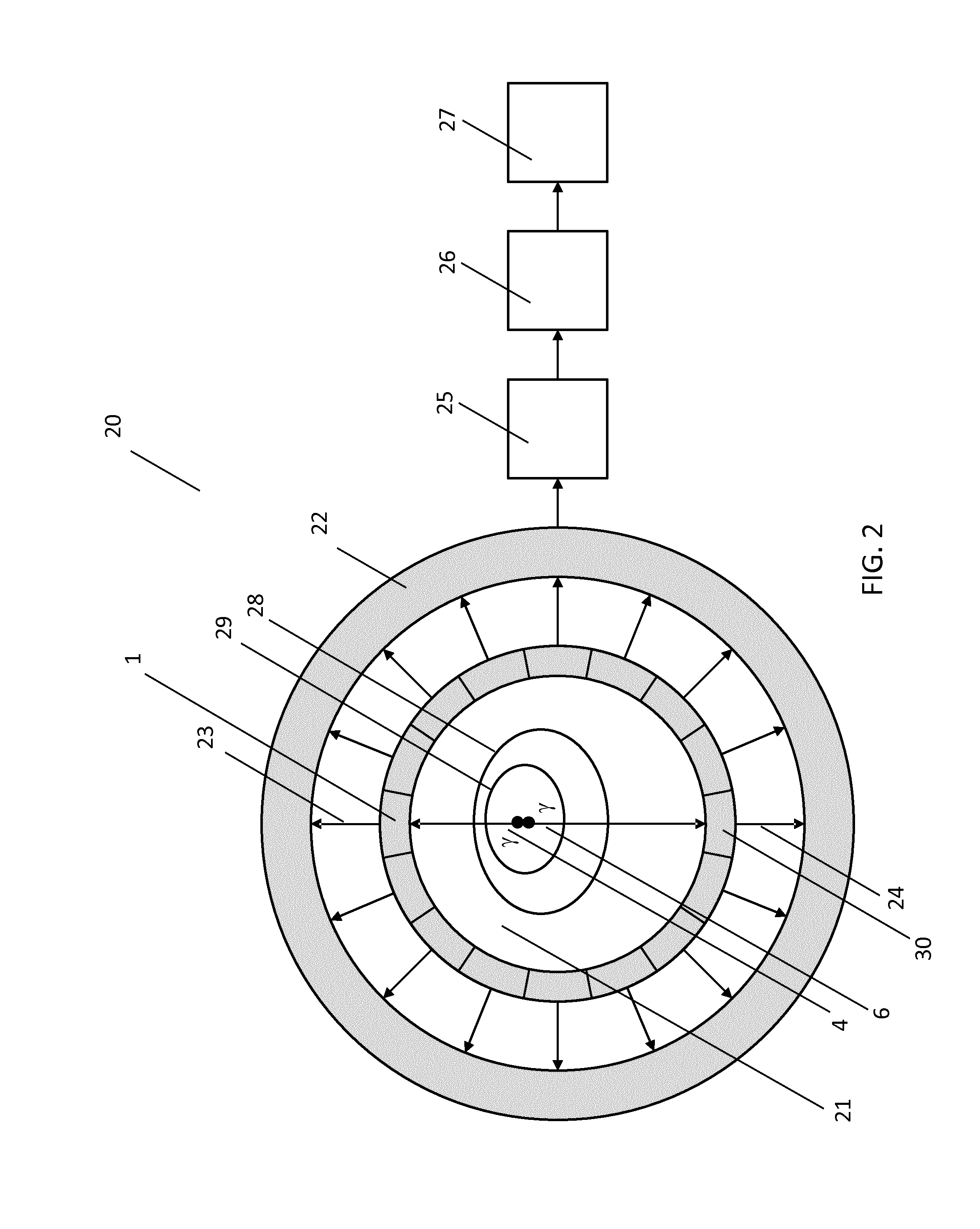
[0055] a scintillator material 2, having exemplary application in a gamma photon detector such as that illustrated in FIG. 1, and having further exemplary application in a PET imaging system illustrated in FIG. 2 has the composition (Gd2.7-yLu0.3Cey)(Al2.5Ga2.47 Lu0.03)O12 wherein the amount of cerium is in the range 0.1 mol % to 1.0 mol %. In this composition the cerium doping is represented by Cey. Improved sensitivity is achieved by further restricting the cerium concentration range, which is progressively reduced throughout the following series of ranges: 0.15 mol % to 1.0 mol %; 0.15 mol % to 0.6 mol %; 0.15 mol % to 0.5 mol %; 0.15 mol % to 0.4 mol %; 0.15 mol % to 0.2 mol %.
[0056]The effect of adding cerium to the garnet composition is to cause the emission of substantially green scintillation light from the garnet with particularly high light yield when struck by gamma photons having an energy that is close to the peak of the scintillation light response. FIG. 3 illustrates ...
seventh embodiment
[0069] the use of any of the scintillator materials disclosed in the first six embodiments is used in optical communication with an optical detector having either a gamma photon receiving area or an active area of less than 5 cm2. The resulting combination is termed a gamma photon detector. Examples of suitable optical detectors include a PMT and a solid state semiconductor optical detector. By further reducing either the gamma photon detector's gamma photon receiving area, or its active area, the gamma photon detector becomes increasingly tolerant of longer decay time scintillator materials in which a lower concentration of cerium is required and in which a higher light yield is achieved. Such areas in the following ranges lead to an increased tolerance of decay time: less than 2.5 cm2; less than 1 cm2; less than 0.5 cm2; less than 0.2 cm2; less than 0.1 cm2.
eighth embodiment
[0070]According to an eighth embodiment, the cerium concentration in any of the scintillator materials disclosed in the first seven embodiments is controlled such that the decay time is in the range 60 ns to 300 ns and the resulting scintillator material is used in optical communication with an optical detector having either a gamma photon receiving area or an active area of less than 5 cm2. The resulting combination is termed a gamma photon detector. In contrast to typical materials assumptions made of scintillator materials, such a range in decay time is tolerable in small-area gamma photon detectors such as for example solid state semiconductor optical detectors used in digital PET.
[0071]According to a ninth embodiment the cerium concentration in any of the scintillator materials disclosed in the first eight embodiments is controlled such that the light yield exceeds 40000 photons / MeV at a gamma photon energy of 511 keV. Such high light yield values indicate high sensitivity to g...
PUM
| Property | Measurement | Unit |
|---|---|---|
| Time | aaaaa | aaaaa |
| Density | aaaaa | aaaaa |
| Area | aaaaa | aaaaa |
Abstract
Description
Claims
Application Information
 - R&D
- Intellectual Property
- Life Sciences
- Materials
- Tech Scout
- Unparalleled Data Quality
- Higher Quality Content
- 60% Fewer Hallucinations
Browse by: Latest US Patents, China's latest patents, Technical Efficacy Thesaurus, Application Domain, Technology Topic, Popular Technical Reports.
© 2025 PatSnap. All rights reserved.Legal|Privacy policy|Modern Slavery Act Transparency Statement|Sitemap|About US| Contact US: help@patsnap.com